Electro-hydraulic brake system and method for controlling the same

a technology of electro-hydraulic brakes and brake pads, which is applied in the direction of braking systems, braking components, transportation and packaging, etc., can solve the problems of large size pumps, difficult to secure sufficient braking power, and high manufacturing costs so as to improve the weight and manufacturing cost of electro-hydraulic brake systems, prevent deterioration of brake stability, and increase the braking distance

Active Publication Date: 2016-12-01
HYUNDAI MOTOR CO LTD
View PDF11 Cites 24 Cited by
  • Summary
  • Abstract
  • Description
  • Claims
  • Application Information

AI Technical Summary

Benefits of technology

[0018]Various aspects of the present invention are directed to providing an electro-hydraulic brake system which may improve the weight and manufacturing cost of the electro-hydraulic brake system according to the related art and prevent deterioration of the brake stability and an increase in the braking distance due to the insufficient braking power when a pump is out of order, and a method for controlling the same.

Problems solved by technology

However, since the electro-hydraulic brake system according to the related art generates and controls the hydraulic pressure required to generate the braking power by using only one pump driven by a motor without regard to the braking condition, the electro-hydraulic brake system requires a large size of a pump.
The pump having a large size has too heavy weight and is very expensive due to a manufacturing problem.
In addition, when a pump is failed, for example, when the motor is out of order, since the braking force is generated only by pedaling force of a driver in emergency, that is, the hydraulic pressure of the backup master cylinder, it is difficult to secure sufficient braking power so that the brake stability is deteriorated and braking distance is increased.

Method used


Image

  • Electro-hydraulic brake system and method for controlling the same
  • Electro-hydraulic brake system and method for controlling the same
  • Electro-hydraulic brake system and method for controlling the same

Examples


Embodiment Construction

[0045]Reference will now be made in detail to various embodiments of the present invention(s), examples of which are illustrated in the accompanying drawings and described below. While the invention(s) will be described in conjunction with exemplary embodiments, it will be understood that the present description is not intended to limit the invention(s) to those exemplary embodiments. On the contrary, the invention(s) is / are intended to cover not only the exemplary embodiments, but also various alternatives, modifications, equivalents and other embodiments, which may be included within the spirit and scope of the invention as defined by the appended claims.

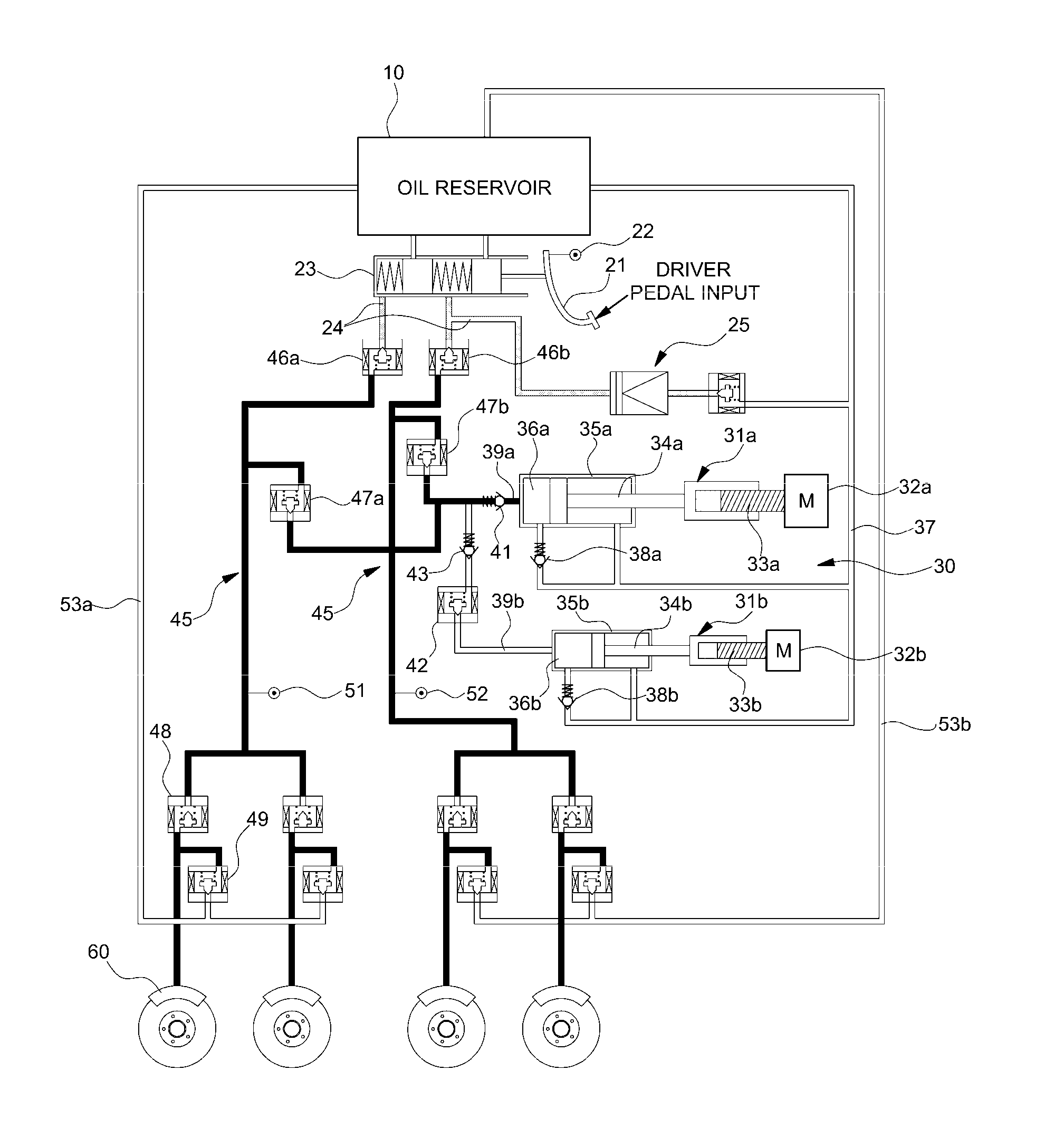
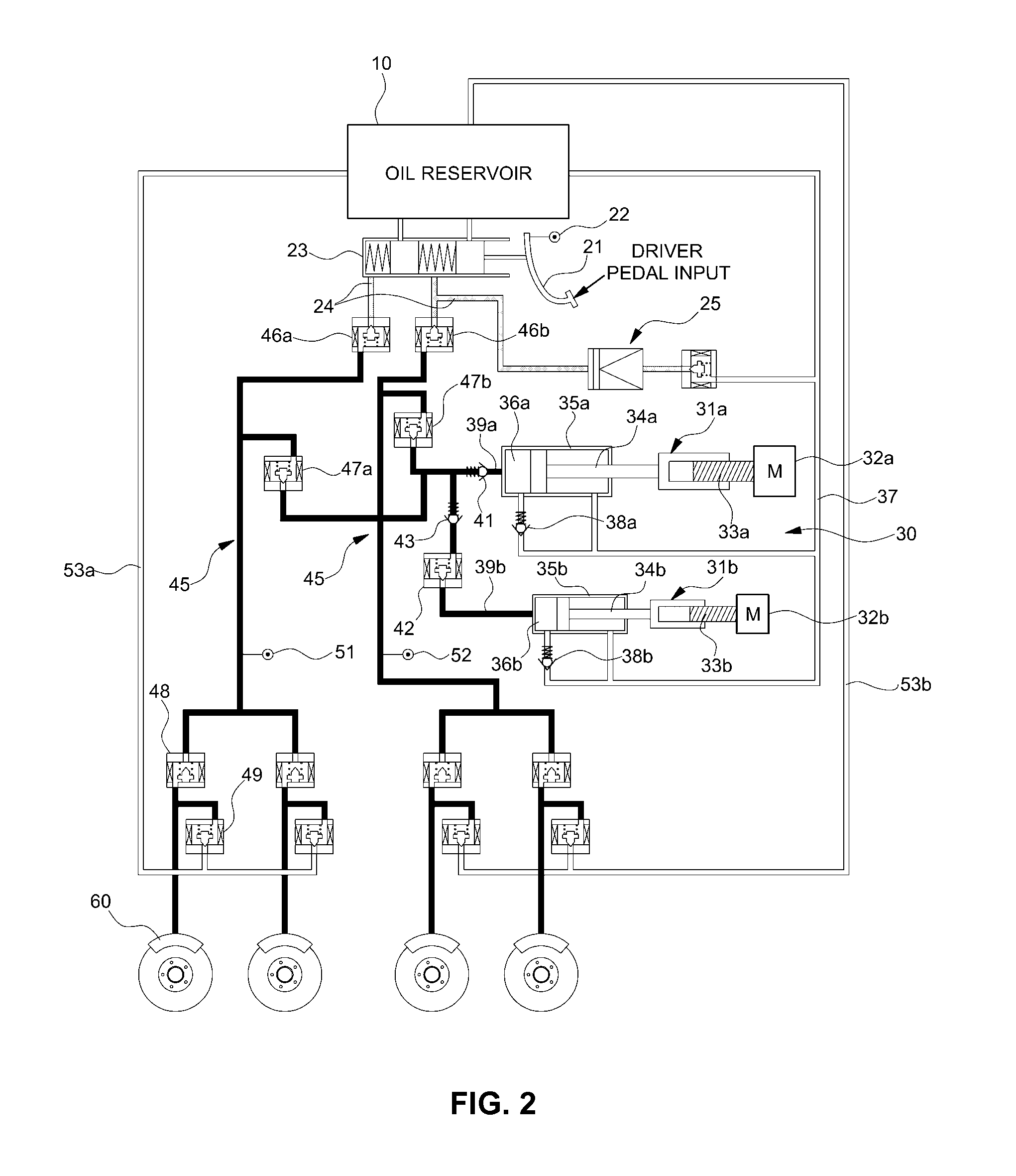
[0046]FIG. 1 is a view illustrating an electro-hydraulic brake system according to various embodiments of the present invention. FIGS. 2 and 3 are views illustrating the operating state of an electro-hydraulic brake system according to various embodiments of the present invention.

[0047]FIGS. 1 and 2 show a state that a brake hydra...


PUM


Abstract

An electro-hydraulic brake system may include a brake input device manipulated by a driver to brake a vehicle, a brake input detecting sensor configured to detect a brake input value of the driver through the brake input device, a pressure generating device configured to generate a brake hydraulic pressure, a wheel cylinder configured to receive the brake hydraulic pressure generated from the pressure generating device and to generate braking power for braking rotations of each vehicle wheel, a hydraulic pressure supply line connected between the pressure generating device and the wheel cylinder to transfer the brake hydraulic pressure generated from the pressure generating device to each wheel cylinder, and a controller configured to output a control signal for controlling an operation of the pressure generating device to allow the pressure generating device to generate a target brake hydraulic pressure based on a signal of the brake input detecting sensor.

Description

CROSS-REFERENCE TO RELATED APPLICATION[0001]The present application claims priority to Korean Patent Application No. 10-2015-0075820 filed May 29, 2015, the entire contents of which is incorporated for all purposes by this reference.BACKGROUND OF THE INVENTION[0002]Field of the Invention[0003]The present invention relates to an electro-hydraulic brake system and a method for controlling the same, and more particularly, to an electro-hydraulic brake system which generates sufficient braking force to secure safety even when a pump for generating a hydraulic pressure necessary to generate braking force is out of order, and a method for controlling the same.[0004]Description of Related Art[0005]Recently, a vehicle brake apparatus has employed a brake-by-wire technique by which, instead of a general hydraulic pressure control system, an electronic control system is applied thereto for control.[0006]Such an electronic control brake apparatus generates the required hydraulic pressure by us...

Claims


Application Information

Patent Timeline
Patent Type & Authority Applications(United States)
IPC IPC(8): B60T13/74B60T8/40B60T13/14
CPCB60T13/745B60T13/142B60T2270/402B60T7/042B60T2270/82B60T8/4081B60T13/12B60T13/66B60T17/22B60T13/166B60T13/662B60T13/686B60T2270/404
Inventor JUNG, YOUNG SUK
Owner HYUNDAI MOTOR CO LTD
Why Eureka
Try Eureka