Electrode sheet for capacitance-type touch panel

a capacitance-type touch panel and electrode-type technology, applied in the field of electrode-type touch panel electrode-type electrode-type sheet, can solve the problems of multi-touch, response speed, and reduced current transfer rate between electrodes, and achieve the effect of high transparency

Active Publication Date: 2016-12-22
NISSHA PRINTING COMPANY
View PDF3 Cites 23 Cited by
  • Summary
  • Abstract
  • Description
  • Claims
  • Application Information

AI Technical Summary

Benefits of technology

[0024]As explained above, according to the electrode sheet for a capacitance-type touch panel of the present invention, the conductive fine line is hardly visible and high transparency can be ensured, even in the case where the electrode is composed of a pattern of an opaque conductive fine line such as a metal fine line.

Problems solved by technology

The surface type one has a simple constitution; however, it is difficult to detect two or more contacts simultaneously (multi-touch).
), and so there is a problem that transfer rate of current between electrodes reduces and response speed (time from contact with a fingertip until detecting its position) is delayed as its applicable size increases.
In addition, since ITO is expensive, it has been a problem of difficulty of the enlargement.

Method used


Image

  • Electrode sheet for capacitance-type touch panel
  • Electrode sheet for capacitance-type touch panel
  • Electrode sheet for capacitance-type touch panel

Examples


first embodiment

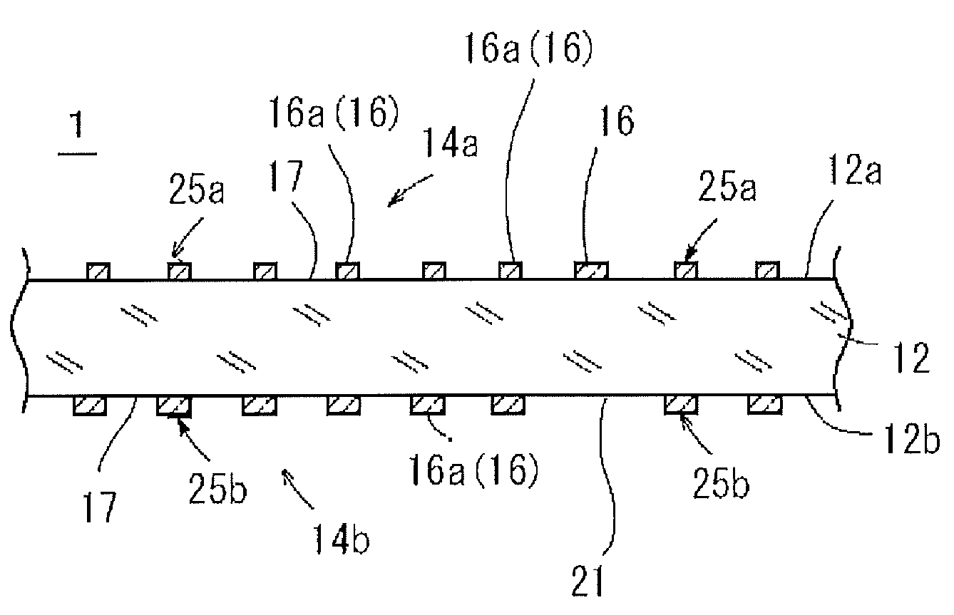
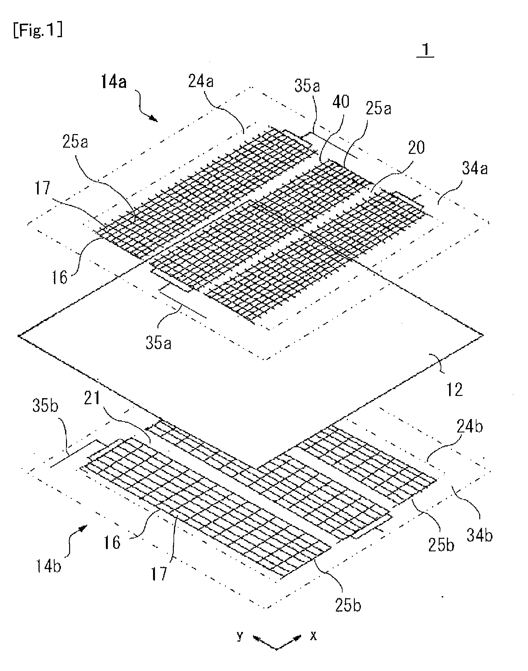
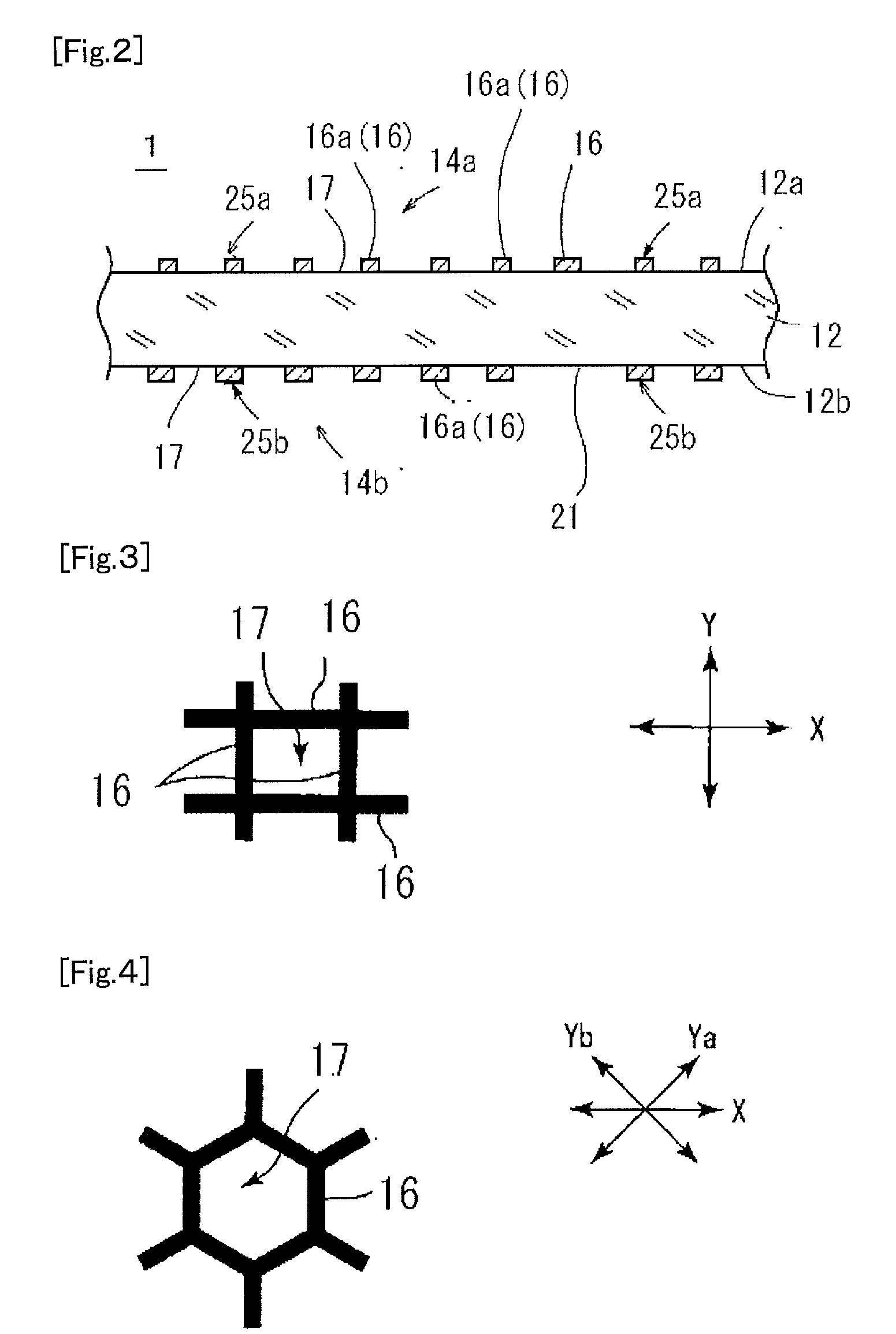
[0043](Constitution of an Electrode Sheet)

[0044]An electrode sheet for a capacitance-type touch panel of a first embodiment comprises a transparent substrate 12, a first conductive part 14a provided on one principal surface of the substrate 12, and a second conductive part 14b provided on the other principal surface of the substrate 12, as shown in FIG. 1. FIG. 2 shows a cross-sectional view of one of a first electrode pattern 25a in the electrode sheet shown in FIG. 1 across a longitudinal direction thereof.

[0045]The substrate 12 is made of a material having an insulating property and high translucency, such as resins, glasses and silicone. Examples of the resin include polyesters such as polyethylene terephthalate (PET), polylactic acid (PLA) and polyethylene naphthalate (PEN), polyolefins such as polyethylene (PE), polypropylene (PP), polystyrene, EVA, cycloolefin polymer (COP) and cyclic olefin copolymer (COC), and others such as vinyl resins, polycarbonate (PC), polyamides, pol...

second embodiment

[0095]In the first embodiment, each of the first electrode pattern 25a and the second electrode pattern 25b has a mesh structure; however, the first electrode pattern 25a and the second electrode pattern 25b are not limited to the mesh structure as long as they are composed of an opaque conductive fine line 16 and a blank part 17 partitioned by the conductive fine line. For example, the second electrode pattern 25b may be formed in a comb-shape in which teeth are arranged in X direction as shown in FIG. 9 (second embodiment), instead of the mesh structure. FIG. 10 shows a cross-sectional view of one of the first electrode pattern 25a in the electrode sheet shown in FIG. 9 across the longitudinal direction thereof.

[0096]In FIG. 9, the line segments 16a facing across the substrate 12 are comprised from teeth of the comb-shape in the second electrode pattern 25b. In the conductive fine line of the first electrode pattern 25a, only a part of the outline of the quadrangle that forms the ...

third embodiment

[0101]In the first embodiment, nothing is provided at the gap 20 between the adjacent first electrode patterns 25a and the gap 21 between the adjacent second electrode patterns 25b in the first conductive part 14a and the second conductive part 14b; however, the present invention is not limited thereto. For example, as shown in FIG. 13, the first conductive part 14a has a plurality of first dummy patterns 55a, that are composed of a conductive fine line 18 made of the same material as the first electrode pattern 25a, placed at the gap 20 between the adjacent first electrode patterns 25a, and insulated electrically from the first electrode pattern 25a; and the second conductive part 14b has a plurality of second dummy patterns 55b, that are composed of a conductive fine line 18 made of the same material as the second electrode pattern 25b, placed at the gap 21 between the adjacent second electrode patterns 25b, and insulated electrically from the second electrode pattern 25b (third e...


PUM


Abstract

A first electrode pattern 25a and a second electrode pattern 25b, each composed of an opaque conductive fine line and a blank part 17 partitioned by the conductive fine line, have line segments 16a of the conductive fine lines 16, that face each other across a substrate 12, and the conductive fine line 16 in one of the first electrode pattern 25a and the second electrode pattern 25b is formed narrower in line width than that in the other of the first electrode pattern 25a and the second electrode pattern 25b only at the facing line segment 16a, thereby designed to have a non-uniform width.

Description

TECHNICAL FIELD[0001]The present invention relates to an electrode sheet for a capacitance-type touch panel in which an electrode is composed of a pattern of an opaque conductive fine line such as a metal fine line.BACKGROUND ART[0002]In general, a capacitance-type touch panel is a position input device which senses a change in capacitance between a human fingertip and a conductive layer to detect a position of the fingertip, and as capacitance-type touch panel, there exists a surface type and a projection type. The surface type one has a simple constitution; however, it is difficult to detect two or more contacts simultaneously (multi-touch). Meanwhile, the projection type one is composed of multiple electrodes arranged in a matrix, and more specifically, it has a constitution that a plurality of first electrodes are arranged in a horizontal direction and a plurality of second electrodes are arranged in its perpendicular direction via an insulating layer, and is able to detect a mu...

Claims


Application Information

Patent Timeline
Patent Type & Authority Applications(United States)
IPC IPC(8): G06F3/041G06F3/044
CPCG06F3/0416G06F3/044G06F2203/04103G06F2203/04111G06F2203/04112G06F3/0445G06F3/0446
Inventor HASHIMOTO, TAKAO
Owner NISSHA PRINTING COMPANY
Why Eureka
Try Eureka