Hydraulic brake system and method for operating a hydraulic brake system

Inactive Publication Date: 2017-01-05
ROBERT BOSCH GMBH
View PDF6 Cites 9 Cited by
  • Summary
  • Abstract
  • Description
  • Claims
  • Application Information

AI Technical Summary

Benefits of technology

[0011]In an advantageous embodiment the second pressure generating device has a hydraulic conveying device that is connected to the hydraulic accumulator and is part of the second pressure generating device. A hydraulic conveying device of this kind is present in the hydraulic assembly in the form of a pump, for example a return delivery pump. The provision of such a pump in the hydraulic assembly additionally makes possible, alongside the known functionalities of wheel pressure modulation in ESP mode, the aforementioned redundancy upon failure of the plunger, and thus enhances safety.
[0012]Advantageously the hydraulic conveying device in the form of the pump of the hydraulic assembly is in hydraulically uncircumventable communication with a further interrupting element. Via the further interrupting element the hydraulic conveying device can be connected to a brake master cylinder in such a way that with the second interrupting means in a closed state, no hydraulic connection exists between the hydraulic conveying device and the brake master cylinder. In contrast to conventional isolation val

Problems solved by technology

With the first interrupting element in a closed position, a hydraulic connection between the first pressure generating unit and the second pressure generating unit is thus no longer possible.
It is also impossible for pressure spikes, or pressure buildup within the hydraulic assembly with the isolation valves closed, to travel via the plunger back to the driver and negatively affect him or her in terms of pedal feel.
Advantageously the hydraulic conveying device in the form of the pump of the hydraulic assembly is in hydraulically uncircumventable communication with a further interrupting element.
In contrast to conventional isolation valves of wheel-pressure-modulating hydraulic assemblies, pulsing at the brake pedal upon operation of the pump is therefore not detectable by the driver, since no hydraulic flow is

Method used


Image

  • Hydraulic brake system and method for operating a hydraulic brake system
  • Hydraulic brake system and method for operating a hydraulic brake system

Examples


Example

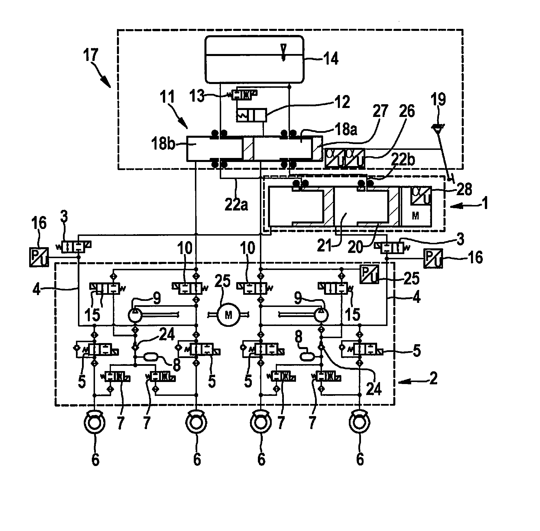
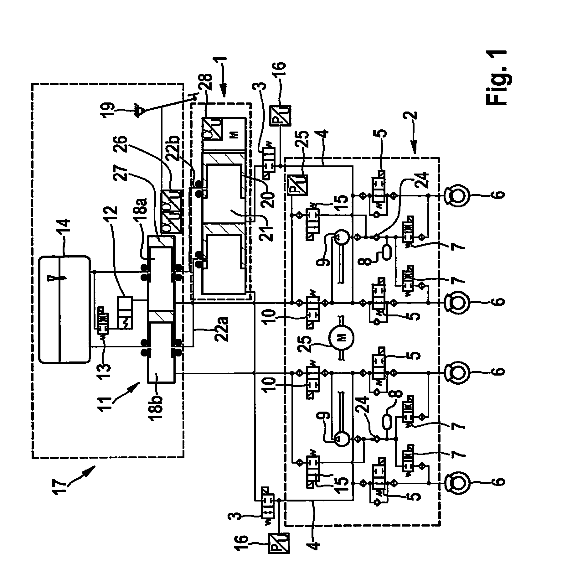
[0021]The braking system according to the present invention encompasses three main elements.

[0022]The braking system encompasses, on the one hand, a brake master cylinder 11 that is supplied with hydraulic fluid from a hydraulic fluid reservoir 14. A brake master cylinder 11 of this kind can be, for example, a conventional tandem brake master cylinder made up of two chambers that are in hydraulic communication with hydraulic fluid reservoir 14 via respective orifices. At least one of chambers 18a and 18b of the brake master cylinder is connected to a pedal simulator 12 that encompasses, for example, a piston-cylinder assemblage as well as an elastic element that can transmit to a driver upon actuation of the braking system a pedal feel that he or she expects upon actuation. A pedal feel is made up, for example, of a pedal force / pedal travel characteristic curve that corresponds to the respective pedal feel. The pedal simulator is furthermore lockable by way of a valve 13 that opens ...


PUM


Abstract

A hydraulic braking system and a method for operating the hydraulic braking system. The hydraulic braking system has a first pressure generating unit and a second pressure generating unit. The first pressure generating unit is hydraulically interruptibly and uncircumventably connected to the second pressure generating unit via a first interrupting element in such a way that with the first interrupting means in a closed position, a hydraulic connection between the first and second pressure generating unit is no longer possible.

Description

BACKGROUND INFORMATION[0001]German Patent Application No. DE 10 2010 040097 A1 describes a braking system for motor vehicles that can be activated both by the vehicle driver and independently of the vehicle driver. The braking system described has, inter alia, an electrohydraulic pressure furnishing device that delivers a braking system pressure, as well as a pressure modulation unit that has, for each wheel brake, an inlet valve as well as an outlet valve for establishing individual-wheel brake pressures. In order to avoid inconvenience to the vehicle driver in particular in the event of a failure of the electrical system of the motor vehicle, it is proposed according to the invention that switch-in valves electrically actuatable for each circuit be interposed between the pressure furnishing device and the pressure modulation unit, which valves, in an activated state, create a hydraulic connection between the pressure furnishing device and the pressure modulation unit.SUMMARY[0002]...

Claims


Application Information

Patent Timeline
IPC IPC(8): B60T8/44B60T8/40
CPCB60T8/4081B60T8/442B60T13/142B60T2270/88B60Y2400/306
Inventor BAUER, URSWILLMANN, KARL-HEINZQUIRANT, WERNER
Owner ROBERT BOSCH GMBH
Why Eureka
Try Eureka