
Aircraft turbine engine air intake duct
a technology of air intake duct and turbine engine, which is applied in the direction of machines/engines, combustion-air/fuel-air treatment, transportation and packaging, etc., can solve the problems of insufficient effectiveness of solution, though functional, and the disturbance of boundary layer shedding that cannot be provided by a device of this type, so as to reduce the distortion in the compressor region, and reduce the effect of shedding
- Summary
- Abstract
- Description
- Claims
- Application Information
AI Technical Summary
Benefits of technology
Problems solved by technology
Method used
Image

Examples
Embodiment Construction
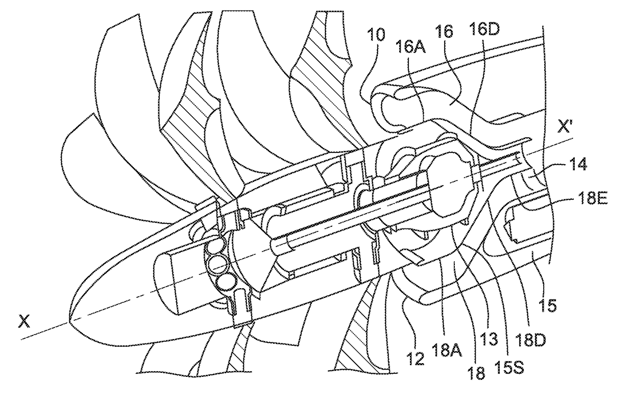
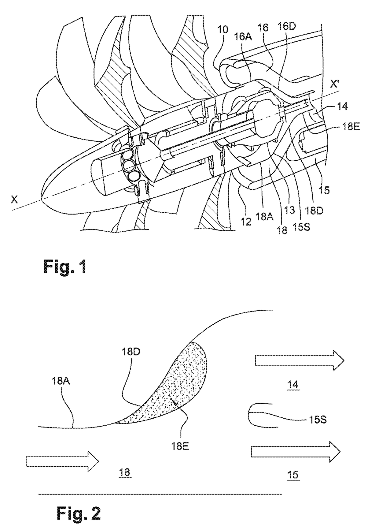
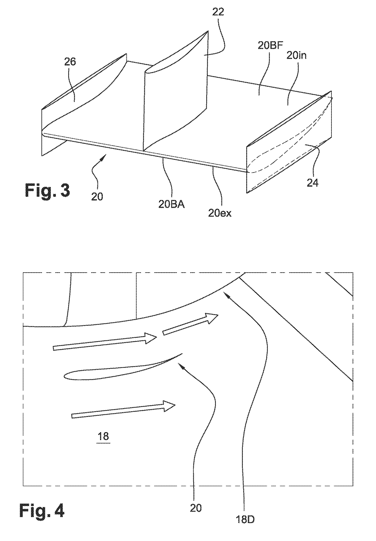
[0026]Reference will first be made to FIG. 1, which shows the front of an example open rotor engine in axial section with a front three-quarter view. The turbine engine comprises two counter-rotating propellers 11 at the front, driven by an engine located in the downstream extension of the axis of the propeller doublet 11. Immediately downstream, two air intakes 10 and 12 on the nacelle supply the gas generator (not shown in the figure) with air. The air intakes 10 and 12 are located on either side of the casing 13—above and below in this case—in which the mechanism for driving and controlling the propellers of the doublet 11 is accommodated. The intakes 10 and 12 communicate with two air intake ducts 16 and 18 having an oblong cross section. These two ducts 16 and 18 converge to a single annular channel 14 that is downstream of said casing 13 and forms the channel 14 for supplying the gas generator with air. Since the two intakes 10 and 12 are radially remote from the engine axis X...
PUM
 Abstract
Description
Claims
Application Information