Fluid electricity generation device with dual-case and rotor assembly thereof

Inactive Publication Date: 2017-07-06
MIYAKE KUNIHIRO +2
View PDF32 Cites 4 Cited by
  • Summary
  • Abstract
  • Description
  • Claims
  • Application Information

AI Technical Summary

Benefits of technology

[0005]The instant disclosure provides a fluid electricity generation device with dual-case and a rotor assembly t

Problems solved by technology

For example, energy generated from the conventional wind electricity generation device depends on a swept area of the blade, so the conventional wind electricity generation device is provided with large blades for increasi

Method used


Image

  • Fluid electricity generation device with dual-case and rotor assembly thereof
  • Fluid electricity generation device with dual-case and rotor assembly thereof
  • Fluid electricity generation device with dual-case and rotor assembly thereof

Examples


Example

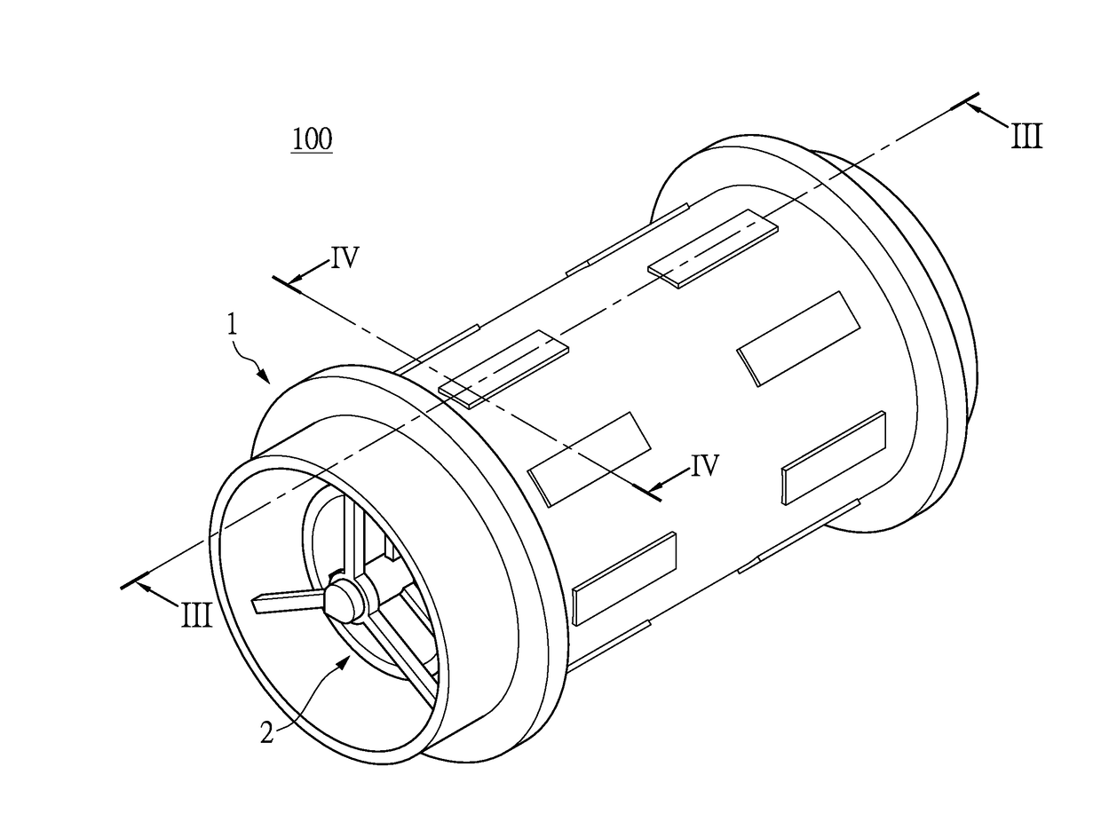
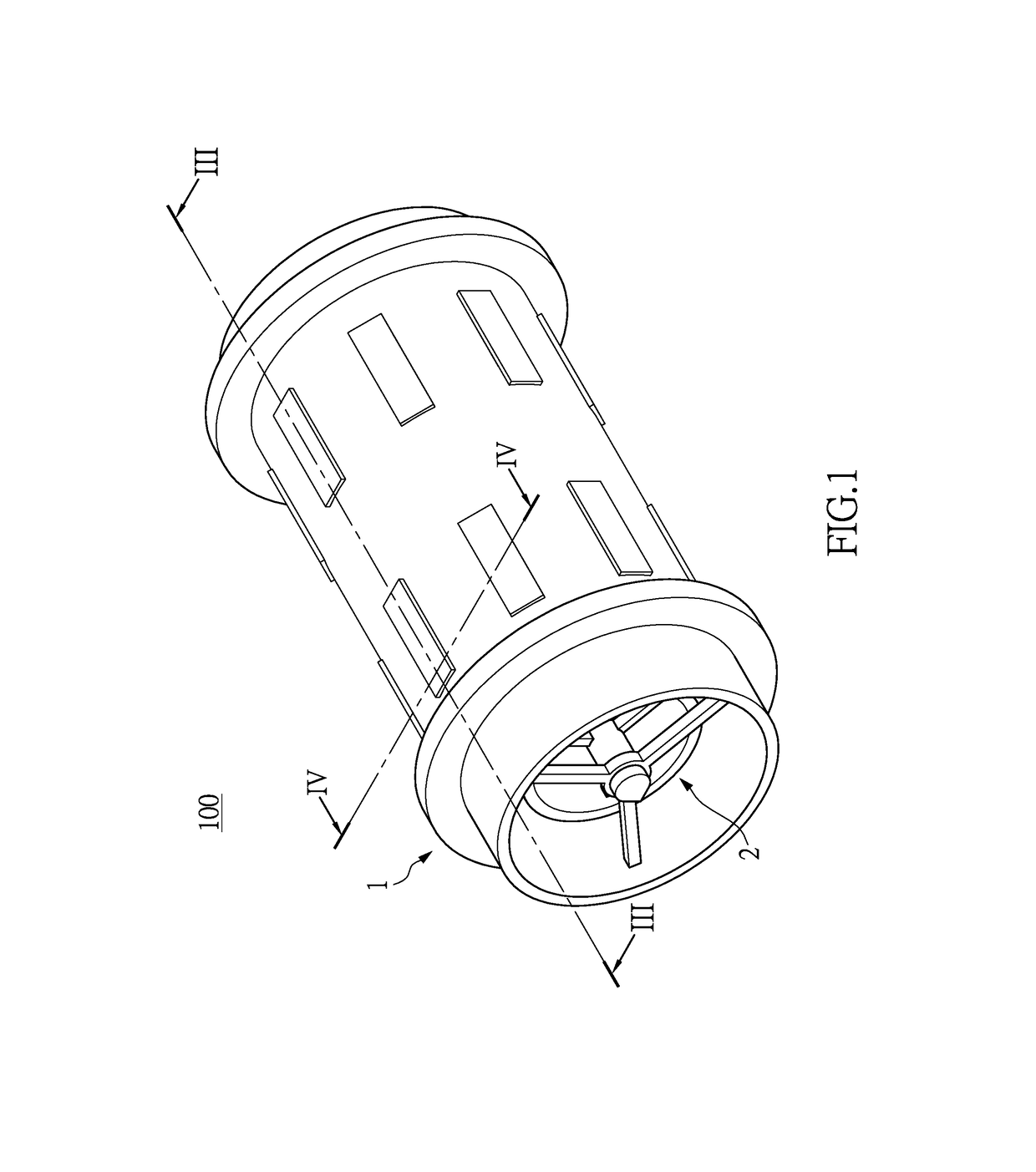
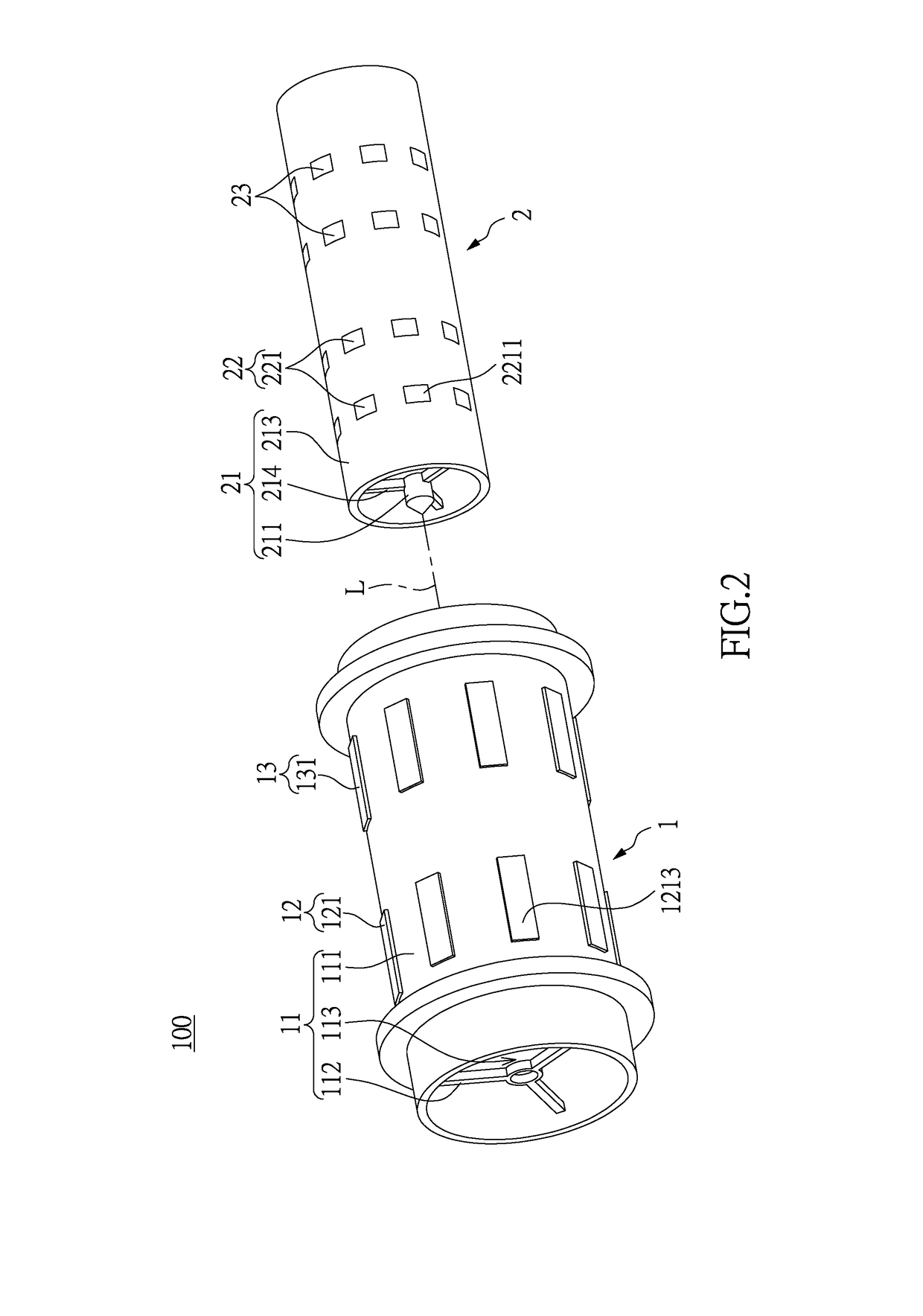
[0025]Please refer to FIGS. 1 through 15, which show an embodiment of the instant disclosure. References are hereunder made to the detailed descriptions and appended drawings in connection with the instant invention. However, the appended drawings are merely shown for exemplary purposes, rather than being used to restrict the scope of the instant invention.

[0026]Please refer to FIG. 1, which shows a fluid electricity generation device 100 with dual-case. The fluid electricity generation device 100 in the instant embodiment is a wind electricity generation device, but is not limited thereto. The fluid electricity generation device 100 comprises a stator assembly 1 and a rotor assembly 2 installed in the stator assembly 1. The rotor assembly 2 is rotatable with respect to the stator assembly 1 for generating electricity. The following description discloses the construction of each one of the stator assembly 1 and the rotor assembly 2, and then discloses the relative features of the st...


PUM


Abstract

A fluid electricity generation device with dual-case includes a stator assembly and a rotor assembly arranged in the stator assembly. The stator assembly includes an outer case and at least one magnetically permeable unit disposed on the outer case. The rotor assembly includes a rotating member and at least one magnetic module. The rotating member has an inner case, a column arranged in the inner case, and a spiral blade connected to the column. The rotating member is rotatable with respect to the outer case. The first magnetic module is disposed on the inner case and has a magnetic area. The spiral blade is configured to be driven to rotate the rotor assembly by utilizing fluid, such that the magnetic area can pass through the magnetically permeable unit for generating induced current.

Description

BACKGROUND OF THE INVENTION[0001]1. Field of the Invention[0002]The instant invention relates to an electricity generation device; in particular, to a fluid electricity generation device with dual-case and a rotor assembly thereof.[0003]2. Description of Related Art[0004]The conventional fluid electricity generation device is provided to generate energy by utilizing fluid to rotate the blade. For example, energy generated from the conventional wind electricity generation device depends on a swept area of the blade, so the conventional wind electricity generation device is provided with large blades for increasing the swept area, but when wind blows the large blades of the conventional wind electricity generation device, the conventional wind electricity generation device does not have a good efficiency of electricity generation. Accordingly, a fluid electricity generation device provided for generating more energy by using a limited fluid force is an important topic in the fluid ele...

Claims


Application Information

Patent Timeline
IPC IPC(8): H02K7/18F03D9/25F03D9/00H02K1/12H02K1/27
CPCH02K7/1823H02K1/12F03D9/25F03D9/002H02K1/274Y02E10/74F03D1/0625H02K21/025H02K1/02H02K1/06H02K1/2753F05B2240/243H02K2213/09F03D15/20Y02E10/72
Inventor MIYAKE, KUNIHIROOMORI, NARIIE
Owner MIYAKE KUNIHIRO
Why Eureka
Try Eureka