Wind electricity generation device and rotor assembly

Inactive Publication Date: 2018-05-24
MIYAKE KUNIHIRO +2
View PDF0 Cites 2 Cited by
  • Summary
  • Abstract
  • Description
  • Claims
  • Application Information

AI Technical Summary

Benefits of technology

[0004]The instant disclosure provides a wind electricity generation device and a rotor assembly for

Problems solved by technology

For example, the conventional wind electricity generation device is provided with large blades for increasing a windward area, but when wind blows the lar

Method used


Image

  • Wind electricity generation device and rotor assembly
  • Wind electricity generation device and rotor assembly
  • Wind electricity generation device and rotor assembly

Examples


Example

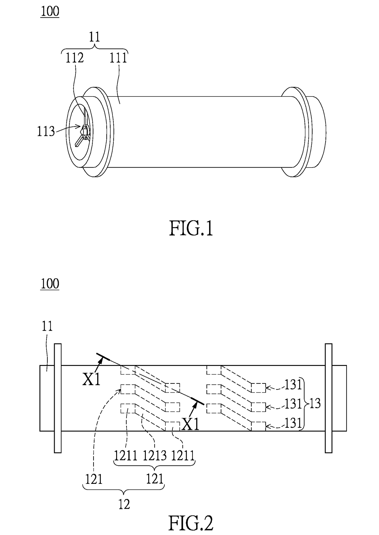
[0027]Please refer to FIGS. 1 through 11, which show a first embodiment of the instant disclosure. References are hereunder made to the detailed descriptions and appended drawings in connection with the instant invention. However, the appended drawings are merely shown for exemplary purposes, rather than being used to restrict the scope of the instant invention.

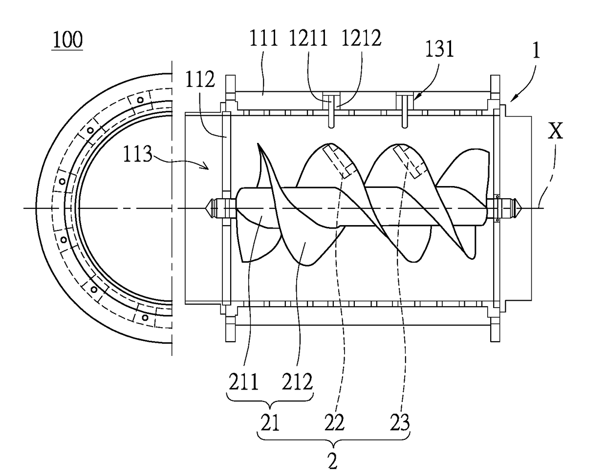
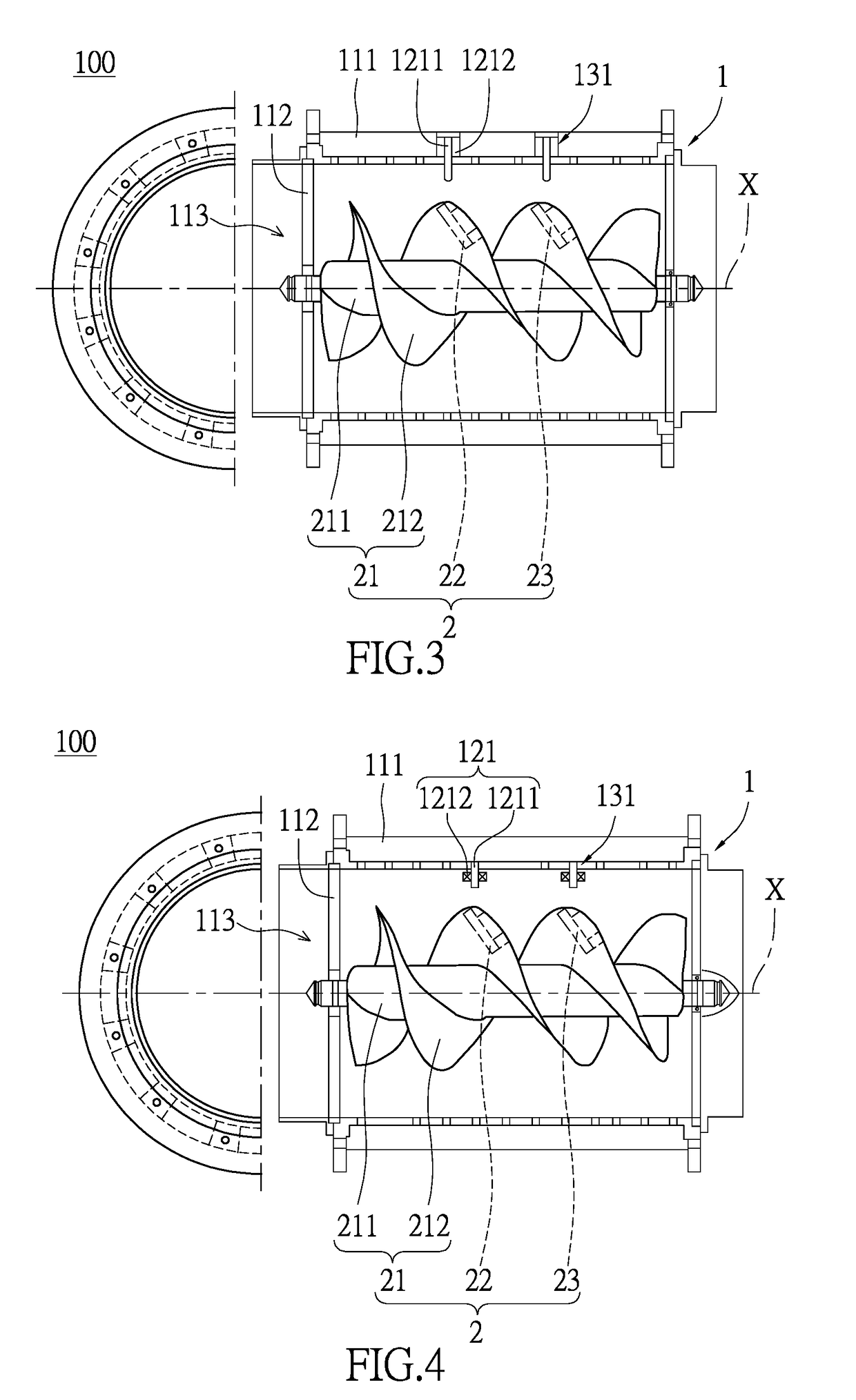
[0028]Please refer to FIGS. 1 through 3, which show a fluid electricity generation device 100. The fluid electricity generation device 100 in the instant embodiment is a wind electricity generation device 100. Moreover, the fluid electricity generation device 100 in the instant embodiment is applied to a vehicle 200 (as shown in FIGS. 10 and 11), but is not limited thereto. The fluid electricity generation device 100 comprises a stator assembly 1 and a rotor assembly 2 installed in the stator assembly 1. The rotor assembly 2 is rotatable with respect to the stator assembly 1 for generating electricity. The following descripti...

Example

Second Embodiment

[0055]Please refer to FIGS. 12 through 14, which show a second embodiment of the instant disclosure. The second embodiment is similar to the first embodiment, so the same features of the two embodiments are not disclosed again. The different features of the two embodiments are disclosed as follows: each magnet block 221 of the first embodiment can move with respect to the corresponding magnetic conductor 222, but the two magnet blocks 221 and the corresponding magnetic conductor 222 of the second embodiment are configured to move simultaneously.

[0056]Specifically, as shown in FIGS. 12 and 13, the first magnetic module 22 in the instant embodiment includes one position adjusting unit 223. The two magnet blocks 221, the magnetic conductor 222, and the position adjusting unit 223 of the first magnetic module 22 are arranged in the same accommodating trough 2121, and the two magnet blocks 221 are respectively connected to two opposite end portions of the magnetic conduc...

Example

Third Embodiment

[0060]Please refer to FIG. 15, which shows a third embodiment of the instant disclosure. The third embodiment is similar to the first embodiment, so the same features of the two embodiments are not disclosed again. The different features of the two embodiments are disclosed as follows: the two magnet blocks 221 in the first embodiment can move with respect to the spiral blade 2121, but the two magnet blocks 221 and the magnetic conductor 222 in the third embodiment cannot move with respect to the spiral blade 2121.

[0061]Specifically, the first magnetic module 22 is provided without any position adjusting unit 223. The two magnet blocks 221 and the magnetic conductor 222 of the first magnetic module 22 are embedded in the spiral blade 2121. The two magnet blocks 221 are respectively connected to two opposite end portions of the magnetic conductor 222, and the magnetic end 2211 of each magnet block 221 is exposed from the edge of the spiral blade 212, but is not limite...


PUM


Abstract

A fluid electricity generation device includes a stator assembly and a rotor assembly. The stator assembly includes a case and a first magnetically permeable unit installed on the case. The rotor assembly includes a rotating member rotatably arranged in the case and a first magnetic module. The rotating member has a column and a spiral blade connected to the column. The first magnetic module is installed on the spiral blade. The first magnetic module has two magnetic ends respectively arranged on two opposite sides thereof, and the first magnetic module emits two kinds of magnetic forces respectively emitted from the two magnetic ends. When the rotor assembly rotates to a position, the magnetic ends respectively face two opposite ends of the first magnetically permeable unit, such that the magnetic forces travel in the first magnetic module and the first magnetically permeable unit to form as a magnetic loop.

Description

BACKGROUND OF THE INVENTION1. Field of the Invention[0001]The instant invention relates to an electricity generation device; in particular, to a wind electricity generation device and a rotor assembly.2. Description of Related Art[0002]The conventional wind electricity generation device is provided to generate energy by utilizing wind to rotate the blade. For example, the conventional wind electricity generation device is provided with large blades for increasing a windward area, but when wind blows the large blades of the conventional wind electricity generation device, the conventional wind electricity generation device usually generates too little energy. Accordingly, a wind electricity generation device provided for generating more energy is an important topic in the wind electricity generation field.[0003]The publication number of related patent is JP 2013-151929.SUMMARY OF THE INVENTION[0004]The instant disclosure provides a wind electricity generation device and a rotor assem...

Claims


Application Information

Patent Timeline
IPC IPC(8): F03D9/25F03D1/04F03D1/06H02K1/30H02K1/27H02K7/18
CPCF03D9/25F03D1/04F03D1/0633H02K1/30H02K1/278H02K7/183F05B2240/221F05B2250/25F05B2240/941F03D9/32Y02E10/20Y02E10/72
Inventor MIYAKE, KUNIHIROOMORI, NARIIE
Owner MIYAKE KUNIHIRO
Why Eureka
Try Eureka