Massage roller mechanism

Active Publication Date: 2020-07-02
WU NA +1
View PDF0 Cites 2 Cited by
  • Summary
  • Abstract
  • Description
  • Claims
  • Application Information

AI Technical Summary

Benefits of technology

[0005]An objective of present invention is to provide a massage rolle

Problems solved by technology

In modern life, people are under various stress and are easily suffer body aches.
However, the current massage chairs, massage beds or lower limb massage devices all have complex massage mechanisms, whic

Method used


Image

  • Massage roller mechanism
  • Massage roller mechanism
  • Massage roller mechanism

Examples


Example

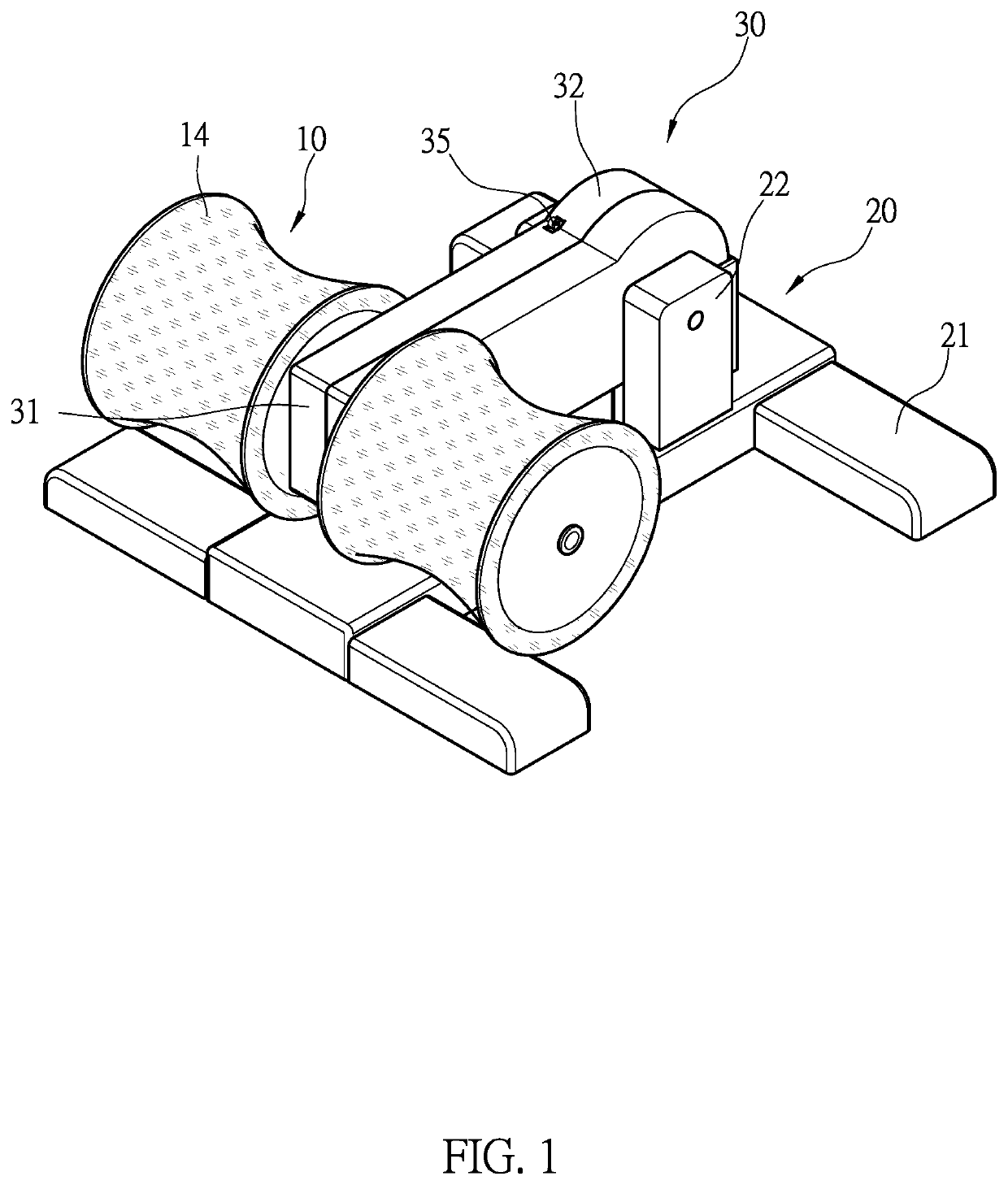
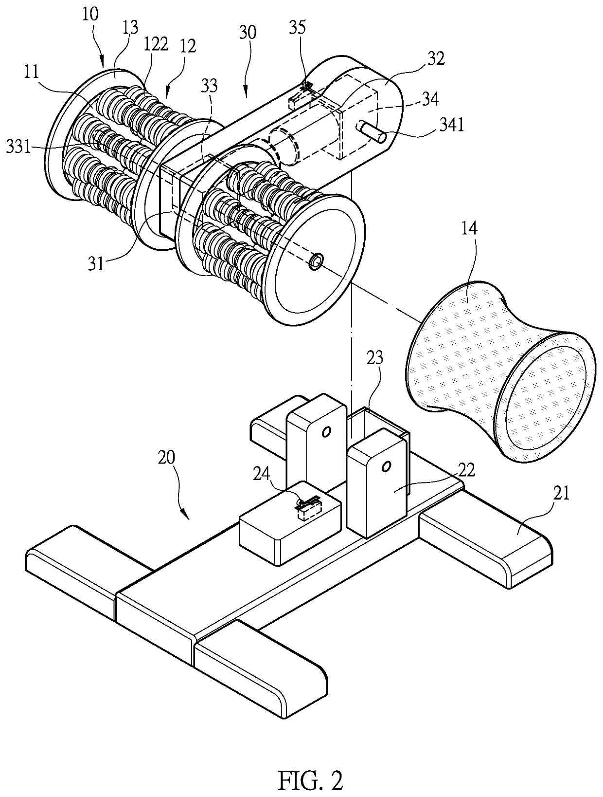
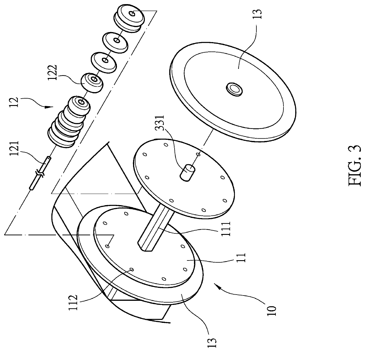
[0021]First, please refer to FIGS. 1-4. A massage roller mechanism 10 comprises two round disks 11 and a plurality of massaging units 12 between the two round disks 11. A shaft 111 connects the two round disks 11 at their center, and a plurality of through apertures 112 are evenly and respectively disposed around the shaft 111 on the two round disks 11. The massaging unit 12 utilizes an elastic band 121 to connect a plurality of massage beans 122, and the massaging units 12 are secured onto each through aperture 112 between the two round disks 11 via the elastic band 12. Each side of the two round disks 11 of the massage roller 10 is provides with an outer disk 13.

[0022]The massage roller 10 is employed in a massage device. Please refer to FIGS. 1-4 again. The rotatable leg massage device comprises: a base 20 and a swinging arm 30. Two sides of the base 20 are each provided with a foot stand 21, and the base 20 further has two opposing assembling posts 22 and a limiting baffle 23 be...


PUM


Abstract

A massage roller mechanism has two round disks and a plurality of massaging units between the two round disks, a shaft connecting the two round disks, a plurality of through apertures evenly and respectively disposed around the shaft on the two round disks. The massaging unit utilizes an elastic band to connect a plurality of massage beans, and the massaging units are secured onto each through aperture between the two round disks via the elastic band.

Description

BACKGROUND of INVENTIONField of Invention[0001]The present invention relates to a massage mechanism, and more particularly to a massage roller mechanism.Description of the Related Art[0002]In modern life, people are under various stress and are easily suffer body aches. Therefore, various massage devices are employed to massage different parts of the body to ease the body tension. The general massage devices are divided into a body massage device such as a massage chair, a massage bed, etc., and a partial massage device such as a shoulder-neck massage belt, a waist massage belt or a calf and foot massage machine, etc. All of them employ rollers, airbags or vibration to generate mechanical press on corresponding body parts to relieve the tension of the muscles.[0003]However, the current massage chairs, massage beds or lower limb massage devices all have complex massage mechanisms, which cause the equipment to be bulky, and it is difficult to place and store. The massage wheels or mas...

Claims


Application Information

Patent Timeline
IPC IPC(8): A61H15/00
CPCA61H2201/1215A61H15/0078A61H2201/1676A61H2015/0021A61H39/04A61H2201/0149A61H2201/1207A61H2201/164A61H2205/10A61H2205/125A61H2015/005A61H1/00A61H2203/0437A61H2201/169A61H2201/1645A61H2203/0456A61H2201/0161A61H2203/0431A61H2205/12A61H2201/1671A61H2015/0014A61H2205/06A61H2201/0165
Inventor WU
Owner WU NA
Why Eureka
Try Eureka