
Partitioned Anti-Falling Connecting Device

Active Publication Date: 2018-12-06
AKILA TECH CO LTD
View PDF1 Cites 2 Cited by
  • Summary
  • Abstract
  • Description
  • Claims
  • Application Information

AI Technical Summary

Benefits of technology

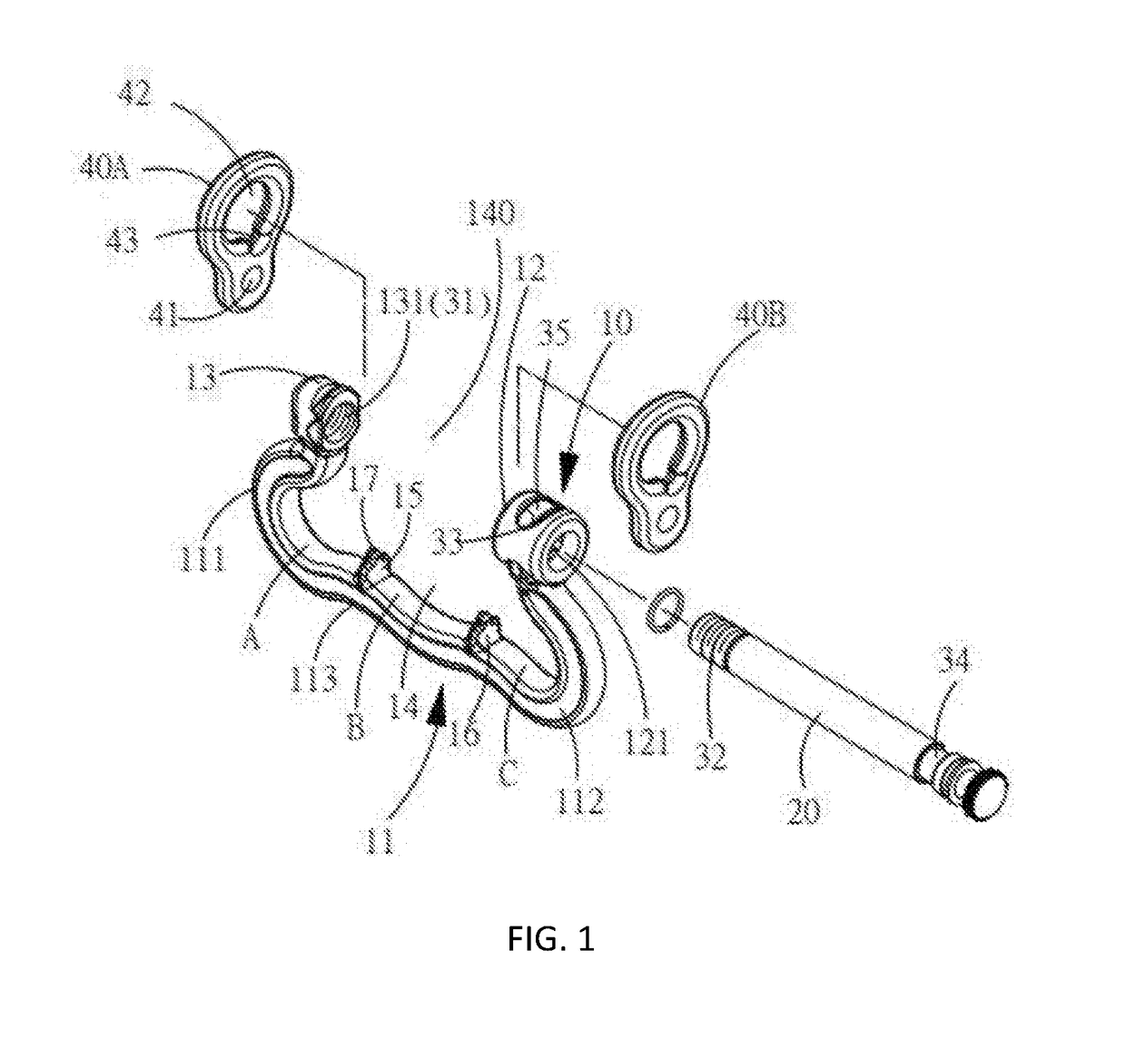
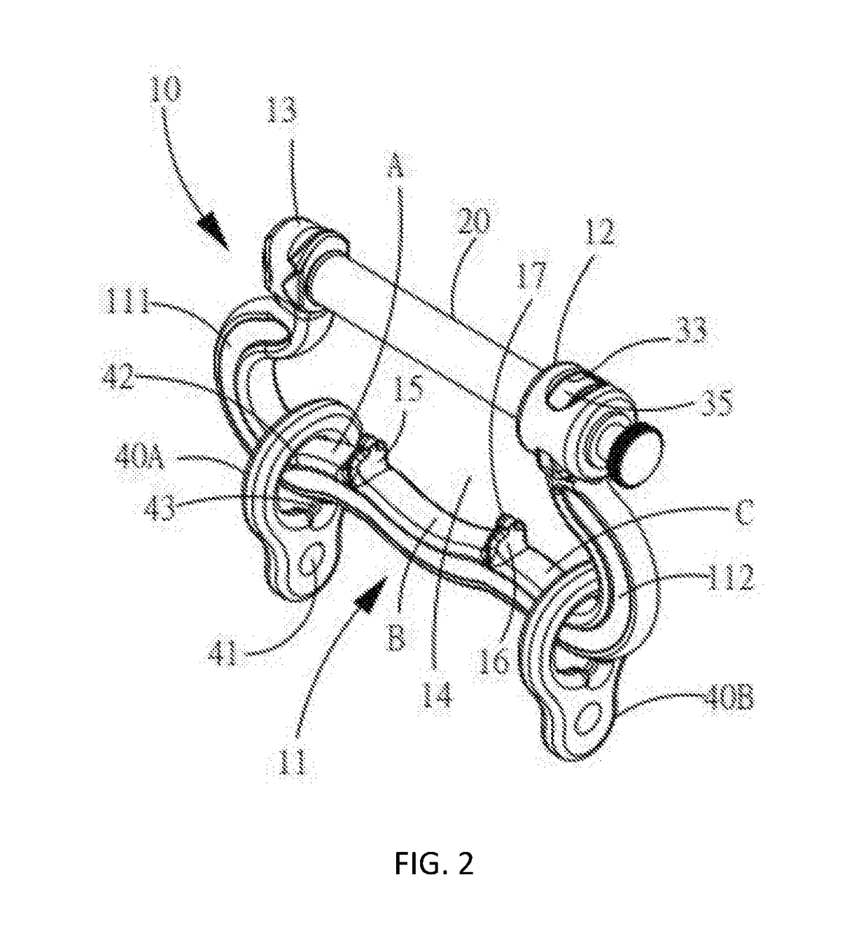
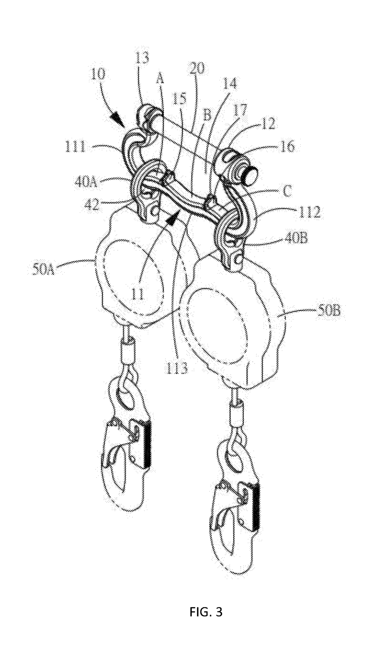
The present invention is a partitioned anti-falling connecting device that includes a frame with a hanging space and a gap between two ends, a movable latch for opening and closing the gap, and at least one hoist ring with a coupling portion for arranging anti-falling device. The hoist ring can be optionally switched between two sections by controlling the loop hole that slides within the frame. This arrangement improves the problem of constant wobble around conventional anti-falling devices and allows the hoist ring to move to the area and position that meet the operational need of the user, enhancing the comfort of the user working at height.

Problems solved by technology

Specifically speaking, when a user moves at height, the anti-falling device can wobble greatly all around along the connecting device and make the user's back very uncomfortable due to lots of friction.
Also, the connecting device according to the prior art has two sets of anti-falling devices arranged thereon at the same time for two-hand operation purpose, but these two sets of anti-falling devices can often bump with each other when the user is moving.
As a result, it not only generates noise that bothers people, but also highly possibly damages the inner structure of the anti-falling device under the long-term constant bumping, which may lead to the failure of the anti-falling device.

Method used


Image

  • Partitioned Anti-Falling Connecting Device
  • Partitioned Anti-Falling Connecting Device
  • Partitioned Anti-Falling Connecting Device

Examples


Embodiment Construction

[0021]The following description is disclosed to enable any person skilled in the art to make and use the present invention. Preferred embodiments are provided in the following description only as examples and modifications will be apparent to those skilled in the art. The general principles defined in the following description would be applied to other embodiments, alternatives, modifications, equivalents, and applications without departing from the spirit and scope of the present invention.

[0022]Referring to FIGS. 1-4, a partitioned anti-falling connecting device according to a preferred embodiment of the present invention is illustrated, which comprises a frame 10, a movable latch 20, a breaking structure, and two hoist rings 40A / 40B.

[0023]The frame 10 comprises an arm 11, a right bushing 12, and a left bushing 13. The arm 11 comprises a bottom bar 113 bridging an opposite bottom end of a left bar 111 and an opposite bottom end of a right bar 112, so as to define a U-shaped hangin...


PUM


Abstract

A partitioned anti-falling connecting device includes a frame, a movable latch and a hoist ring. The frame has a hanging space with a gap defined between two ends thereof and at least a division island protrudingly arranged between the two ends thereof so as to divide the frame into at least a first section and a second section. The movable latch is arranged on the frame for opening and closing the gap. The hoist ring comprises a coupling portion for arranging an anti-falling device, wherein the top of the coupling portion has a loop hole corresponding to the frame to insert, such that the loop hole is in allowed to be slidingly arranged between the two ends of the frame and, when affected by gravity, to be restricted by the division island, such that the hoist ring is limited in the first section or the second section, wherein when the effect of gravity is overcome, the loop hole is allowed to be controlled to pass the division island, so as to allow the hoist ring to be optionally switched between the first section and the second section, such that the anti-falling device can be adjusted to the area and position that meet the operational need of the user the most.

Description

NOTICE OF COPYRIGHT[0001]A portion of the disclosure of this patent document contains material which is subject to copyright protection. The copyright owner has no objection to any reproduction by anyone of the patent disclosure, as it appears in the United States Patent and Trademark Office patent files or records, but otherwise reserves all copyright rights whatsoever.BACKGROUND OF THE PRESENT INVENTIONField of Invention[0002]The present invention relates to a connecting device for arranging anti-falling device, and more particularly to the technical field that controls wobble of the anti-falling device.Description of Related Arts[0003]Conventional connecting device is illustrated in Taiwan Patent No. 104205356 “Falling Prevention Connecting Device” and Taiwan Patent No. 105206516 “Locking Type Connection Device for Preventing from Falling.” However, the inventor of the present invention discovers the drawbacks of these prior cases. Specifically speaking, when a user moves at heig...

Claims


Application Information

Patent Timeline
IPC IPC(8): A62B35/00
CPCA62B35/0068A62B35/0037
Inventor YANG, KAI CHIEHHUANG, CHIA CHENG J.
Owner AKILA TECH CO LTD
Learn More