Orthotic appliance with continuously adjustable positioning of corrective elements

Inactive Publication Date: 2018-08-09
MOTION THERAPEUTICS
View PDF5 Cites 1 Cited by
  • Summary
  • Abstract
  • Description
  • Claims
  • Application Information

AI Technical Summary

Benefits of technology

[0014]It will be appreciated that, although a particular of arrangement of “layers” is described herein, layers may be combined or added while still achieving a desired compressive tension effect in both the panels that receive the corrective elements and the non-corrective-element receiving panels to which they are assembled, and further that the term “layers” may encompass both single and multiple ply fabric layers.
[0015]During assembly, the panels are preferably assembled together under tension. Although assembly under tension is not necessary to achieve a compression effect, the addition of tension by differential stretching of the panels as they are assembled together, enables a compression gradient to be achieved without the need to vary the stiffness of the panels using different materials. By increasing the tension in areas where the corrective elements are to be attached, compression is increased i

Problems solved by technology

This patent, however, does not provide for continuous adjustment of weight positions, but rather utilizes pockets to hold individual weights at discrete positions.
Furthermore, the patent describes a unitary construction that is incapable of providing differential compression.
However, U.S. Pat. No. 9,445,932 does not apply the differential compression to help secure corrective elements, and there is no disclosure of achieving the compressive tension during manufacture by subjecting panels to different tensile loads as they are stitched together, rather than by using material of different stiffness.
As a result, the proprioceptive feedback provided by the garment disclosed in U.S. Pat. No. 9,445,932 cannot be adjusted by a clinician or user

Method used


Image

  • Orthotic appliance with continuously adjustable positioning of corrective elements
  • Orthotic appliance with continuously adjustable positioning of corrective elements
  • Orthotic appliance with continuously adjustable positioning of corrective elements

Examples


Embodiment Construction

[0025]Throughout the following description and drawings, like reference numbers / characters refer to like elements. It should be understood that, although specific exemplary embodiments are discussed herein there is no intent to limit the scope of present invention to such embodiments. To the contrary, it should be understood that the exemplary embodiments discussed herein are for illustrative purposes, and that modified and alternative embodiments may be implemented without departing from the scope of the present invention.

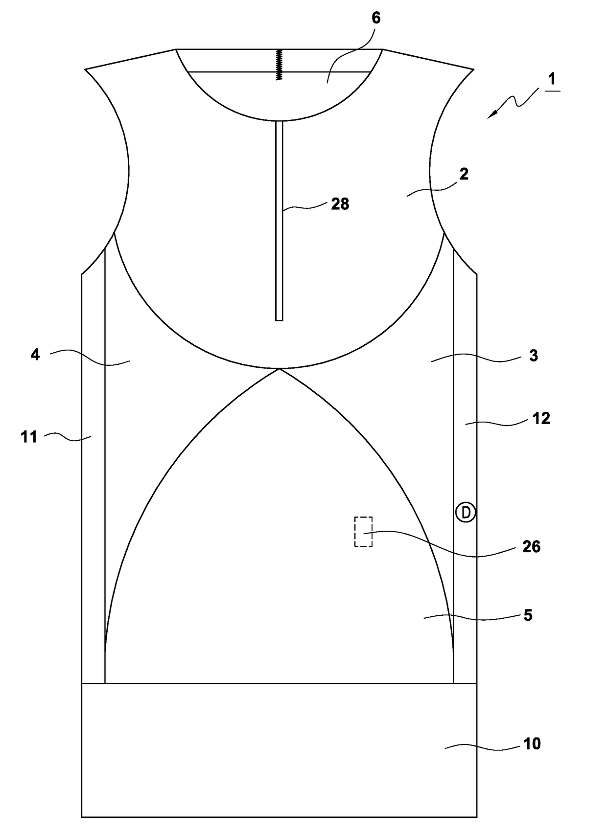
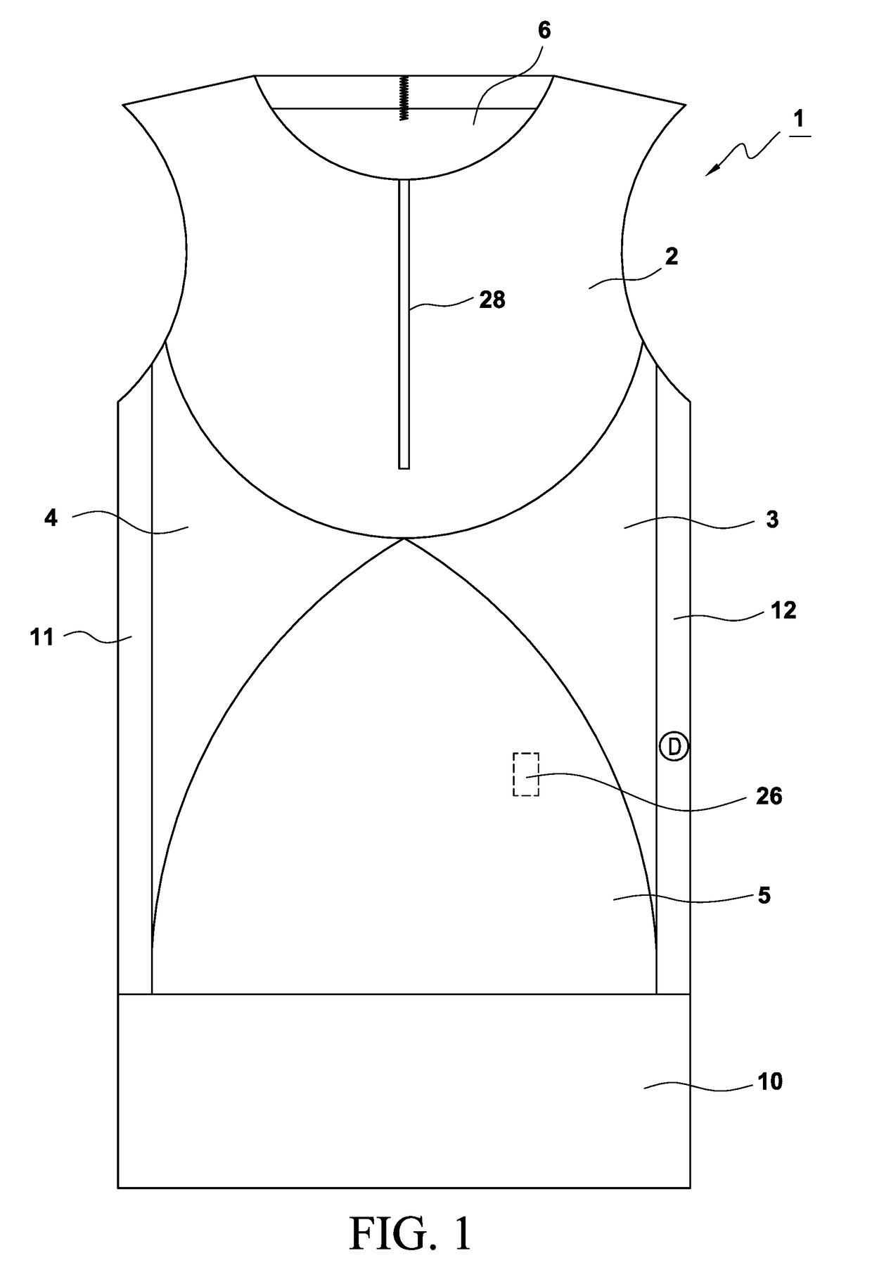
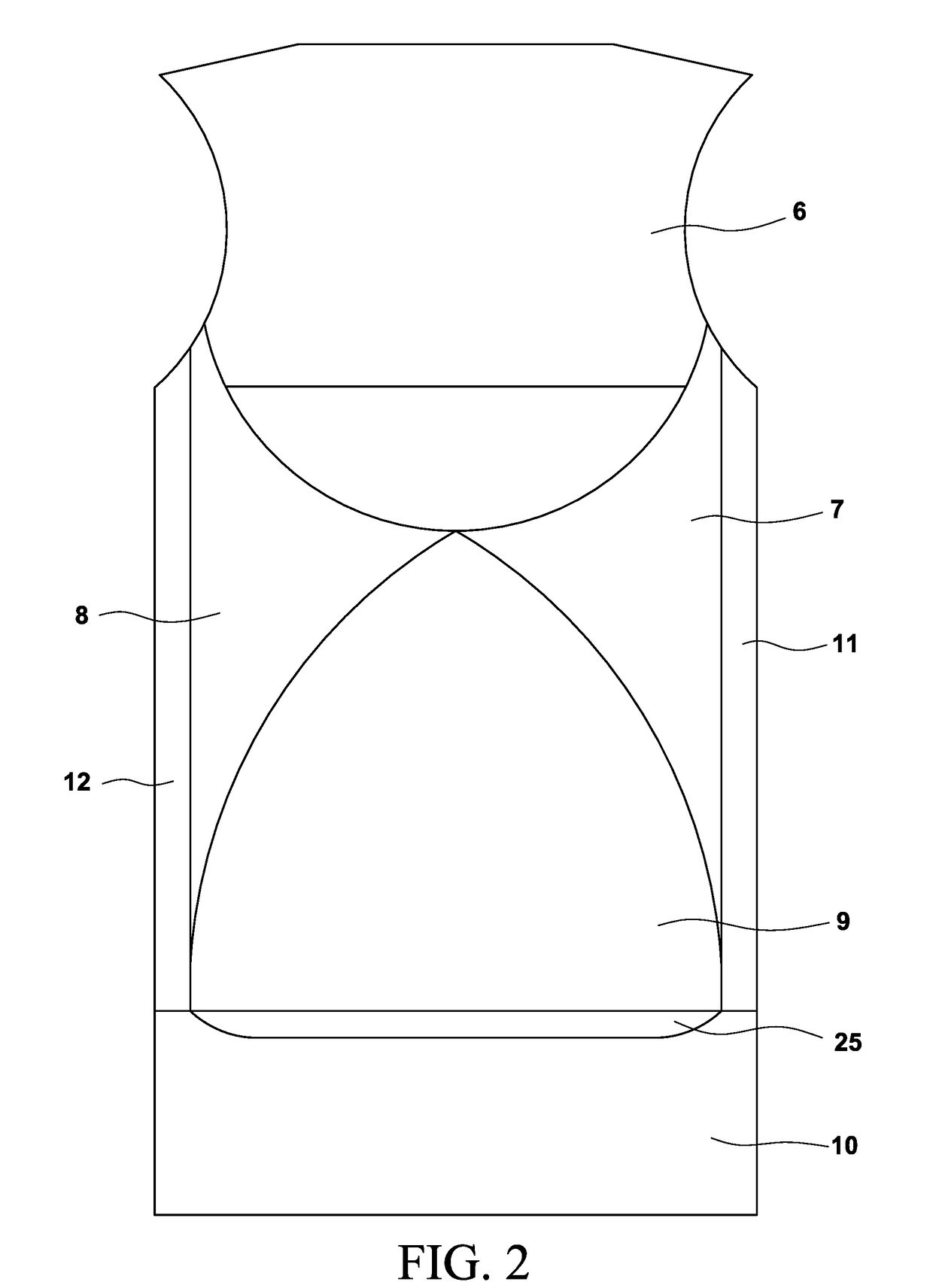
[0026]Although the present invention applies generally to an orthotic appliance, a preferred embodiment of the invention is in the form of a garment such as a vest or shirt. As illustrated in FIGS. 1 and 2, the weighted garment 1 constructed in accordance with the principles of a preferred embodiment of the invention is made of a light weight, breathable elastomeric material. The material may be a Lycra®, Spandex®, or Lycra®-Spandex® material, or another lightweig...


PUM


Abstract

A wearable orthotic appliance to which at least one corrective element for correcting neuromuscular imbalances may be removably attached is made of fabric assembly held in compressive tension when worn by a user, the fabric assembly including a cavity or chamber into which the corrective element may be placed and secured at any of a plurality of continuously-adjustable positions. Maintenance of the corrective element position during use of the appliance may be assisted by establishing a compression gradient over selected areas of the appliance during assembly. The wearable orthotic appliance may be a shirt, vest, body suit, or other garment or article of clothing, and the corrective elements may be weights, electrodes, or other discrete elements whose therapeutic effect depends on proper positioning relative to the wearer's torso or other body parts.

Description

BACKGROUND OF THE INVENTION1. Field of the Invention[0001]The invention relates to a wearable orthotic appliance to which corrective elements for correcting neuromuscular imbalances may be removably attached at therapeutically effective locations. The wearable orthotic appliance may be a shirt, vest, body suit, or other garment or article of clothing, and the corrective elements may be weights, electrodes, vibration-causing transducers, or other discrete elements whose therapeutic effect depends on proper positioning relative to the wearer's torso or other body parts.[0002]The invention also relates to a wearable orthotic appliance in which corrective elements have been positioned by a process involving a clinician applying stimuli to an individual, observing individual reaction to the stimuli, positioning at least one weight in a cavity provided in the appliance, again applying the stimuli to the individual and observing the individual's reaction, and adjusting a position of the at...

Claims


Application Information

Patent Timeline
IPC IPC(8): A61F5/02A61B5/00A61N1/04A61H1/00
CPCA61F5/024A61B5/0053A61H2201/165A61N1/0484A61H1/00A61B5/0057A61N1/0452A61H1/008A61H23/008A61H2201/1621A61H2201/1626A61B5/18
Inventor GIBSON-HORN, CYNTHIAPEARSON, DAVIDSUNDERLAND, MARKLESHER, ANDREWABBEY, ELLE
Owner MOTION THERAPEUTICS
Why Eureka
Try Eureka