
Seat Securing Apparatus

Inactive Publication Date: 2009-08-06
BLUE LEAF I P
View PDF25 Cites 0 Cited by
  • Summary
  • Abstract
  • Description
  • Claims
  • Application Information

AI Technical Summary

Benefits of technology

[0008]An advantage of the present invention is a reduction of time associated with accessing components disposed beneath a work vehicle having a cab.
[0009]A further advantage of the present invention is enhanced comfort for a work vehicle operator, in that restraint devices mounted to a cab structure do not move independently of a seat, in response to both of the cab structure and seat being disposed in an operating position with a frame of a work vehicle.

Problems solved by technology

The removal of the bolts fastening the seat to the loader frame, and the subsequent re-insertion of the bolts to properly replace the seat, requires a significant amount of time, particularly in comparison to the normal time required for minor servicing of these components.

Method used


Image

  • Seat Securing Apparatus
  • Seat Securing Apparatus
  • Seat Securing Apparatus

Examples


Embodiment Construction

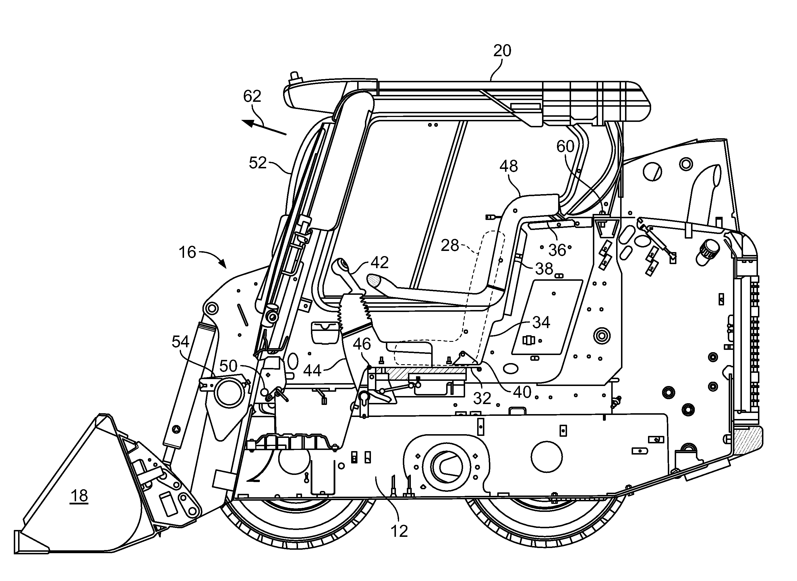
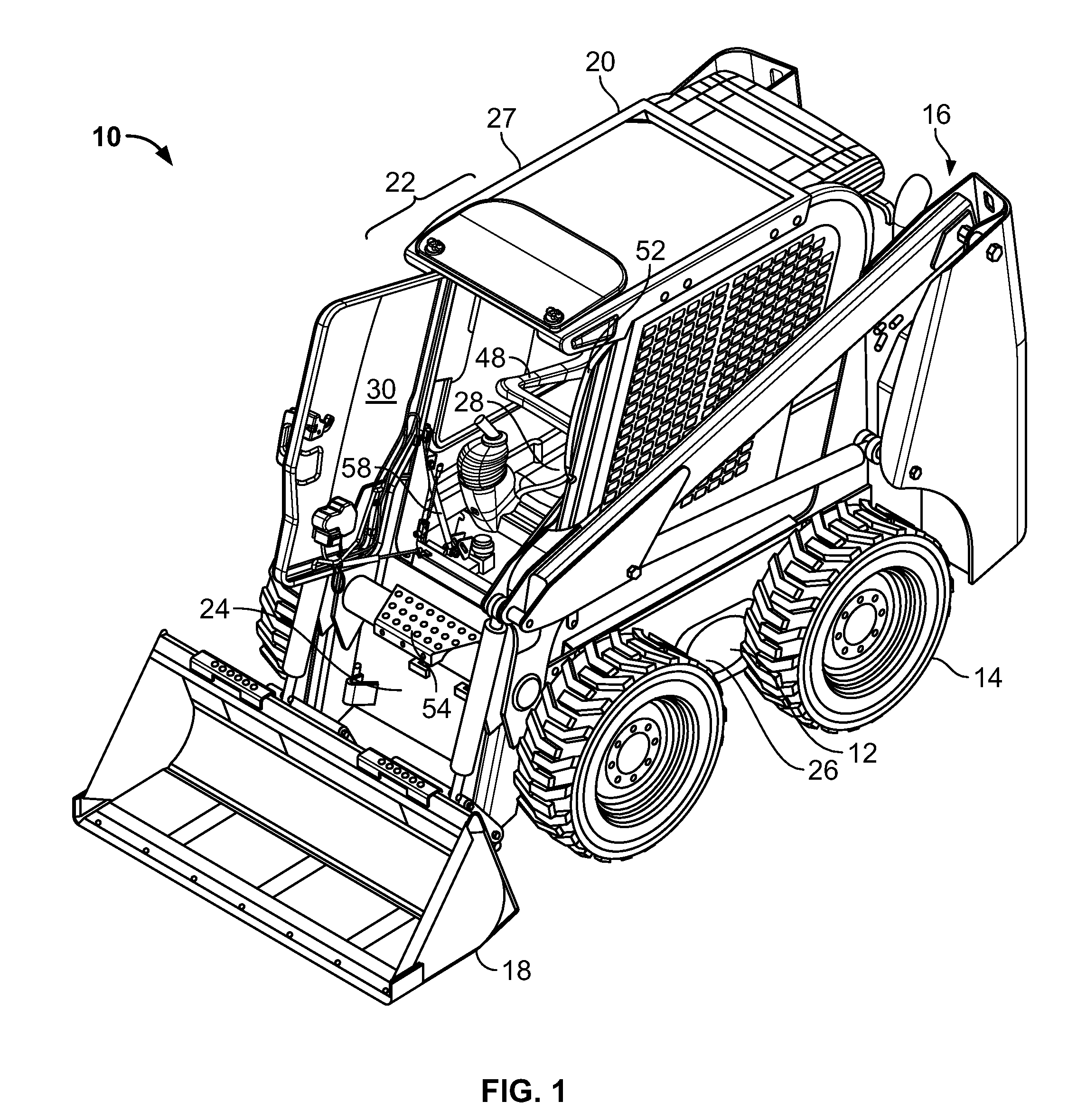
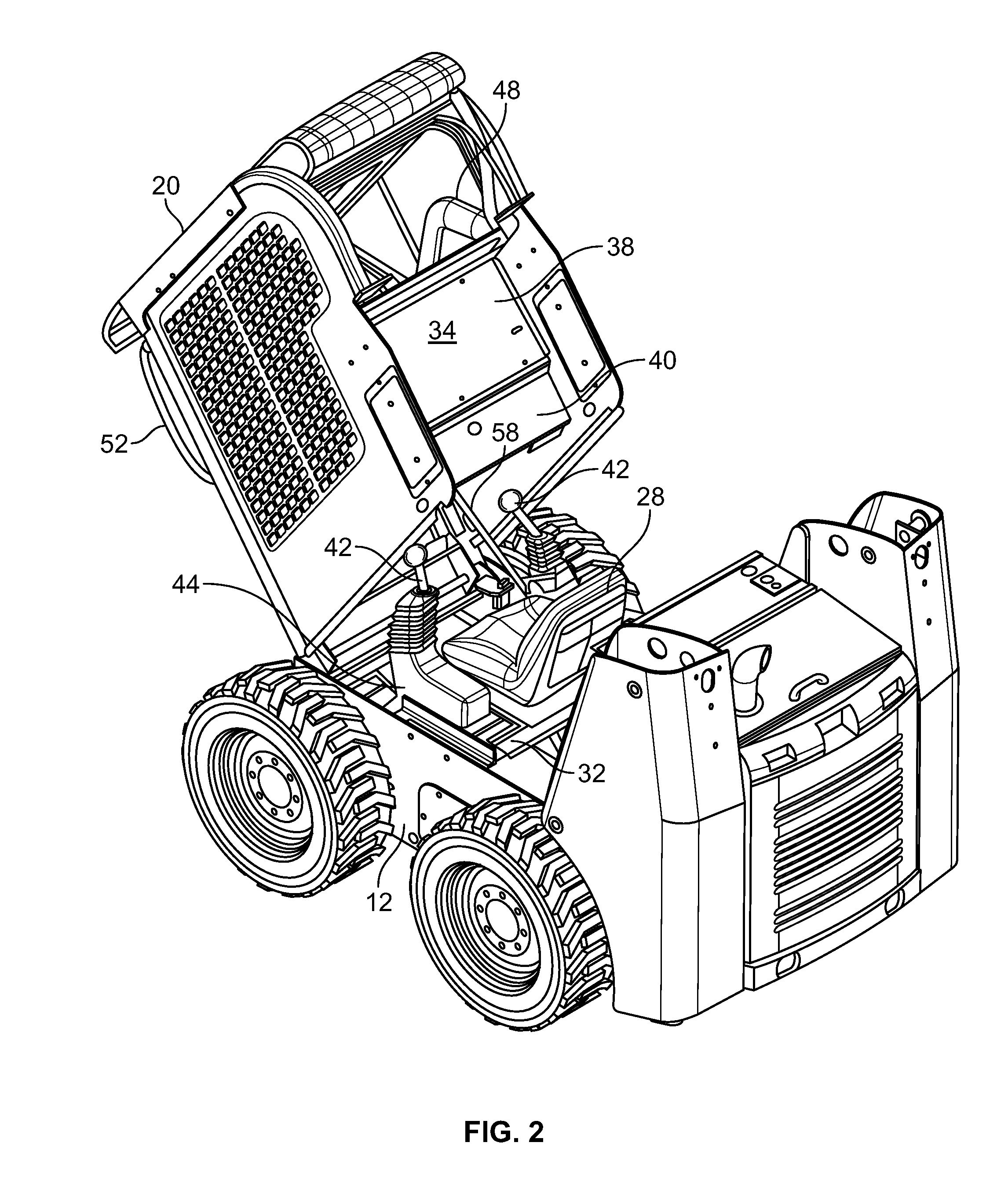
[0018]FIG. 1 shows an exemplary work vehicle 10 including a frame 12 that rotatably carries a plurality of wheels 14. A lifting structure 16 including an arrangement of structural members and actuators controllable by an operator (not shown) to manipulate an implement 18 to perform work is also connected to the frame 12. Frame 12 structurally supports a cab structure 20 to surround and protect the operator, which frame 12 includes a front end 24 facing implement 18. Front end 24 is disposed between opposed sides 26, 27. As further shown in FIG. 1, cab structure 20 includes a brim 22 protruding toward front end 24, although in an alternate embodiment, brim 22 or additional brims may extend toward opposed sides 26, 27 or toward the end opposite end 24. A seat 28 is disposed interior of cab structure 20 which is accessible via a door 30. Door 30 is pivotably connected to cab structure 20. As will be discussed in further detail below, both seat 28 and cab structure 20 are pivotably conn...


PUM


Abstract

A work vehicle includes a frame, and a cab structure and a seat each pivotably connected to the frame. In response to the cab structure and seat being disposed in an operating position with the frame, the cab structure substantially prevents pivotable movement of the seat.

Description

FIELD OF THE INVENTION[0001]The present invention relates generally to the field of work vehicles. It relates more particularly to securing a seat of a work vehicle.BACKGROUND OF THE INVENTION[0002]Work vehicles, such as skid steer loaders, have longitudinally spaced pairs of wheels rotatably carried by a frame or chassis of the loader to permit a driving rotation thereof. Each of the wheels is driven, usually by hydraulic motors powered from an engine supported by the frame of the loader. Steering of the skid steer loader is accomplished by powering the rotation of the wheels on opposing sides of the frame of the loader at differential speeds.[0003]Typically, the hydraulic motors and associated linkages are located beneath the seat of the skid steer loader. To service the apparatus beneath the seat, it is necessary to remove the seat from the loader, which is usually accomplished by unbolting the seat from the frame and physically relocating the seat out of the relatively small ope...

Claims


Application Information

Patent Timeline
IPC IPC(8): B60N3/00
CPCB60N2/24B60N2/10
Inventor CASE, MICHAEL DAVIDBRENNER, KYLEWEINSCHENK, LORAS LAVERN
Owner BLUE LEAF I P
Learn More