Gas turbine blade and manufacturing method

Active Publication Date: 2017-07-20
GENERAL ELECTRIC TECH GMBH
View PDF0 Cites 2 Cited by
  • Summary
  • Abstract
  • Description
  • Claims
  • Application Information

AI Technical Summary

Benefits of technology

[0003]An aspect provides a blade for a gas turbine, the blade comprising a trailing edge and a trailing edge cooling channel extending from a first upstream end to a second downstream end, in which the width of the trailing edge cooling channel in the direction perpendicular to the cambe

Problems solved by technology

Gas turbine blades in modern gas turbine engines are extremely complicated and include various aerodynamic a

Method used


Image

  • Gas turbine blade and manufacturing method
  • Gas turbine blade and manufacturing method
  • Gas turbine blade and manufacturing method

Examples


Embodiment Construction

[0021]Some gas turbine designs, particularly iterative designs made by the same manufacturer, may have the same overall blade size and blade attachment as blades in previous designs; in other words, it may be physically possible to insert a blade designed for one design of gas turbine into another design of gas turbine. However, aerodynamic features of the actual blade need to be a particular size or shape depending on factors that vary between designs such as hot gas flow capacities and pressure ratios, and therefore different blade designs are needed in different designs of gas turbine.

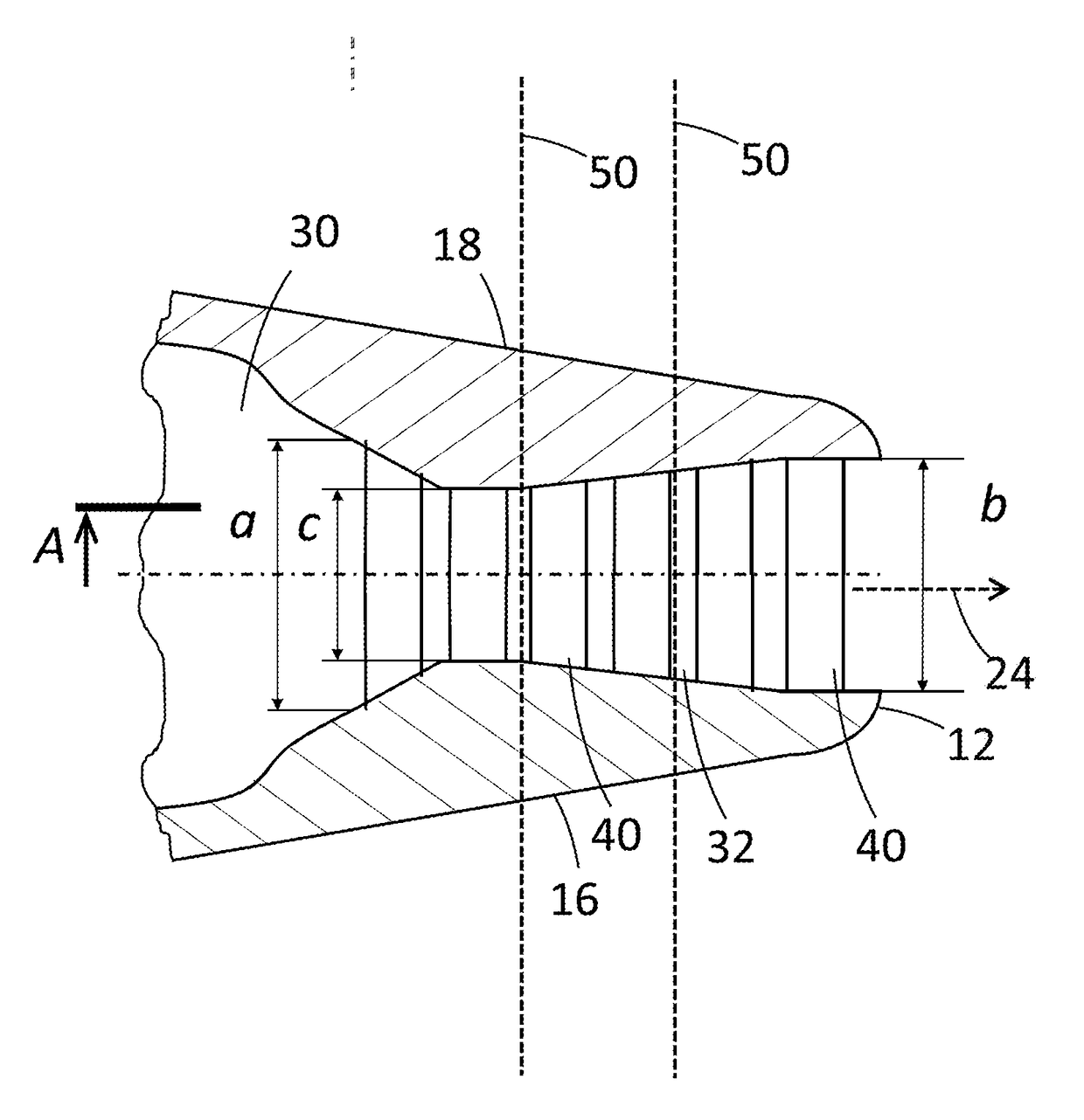
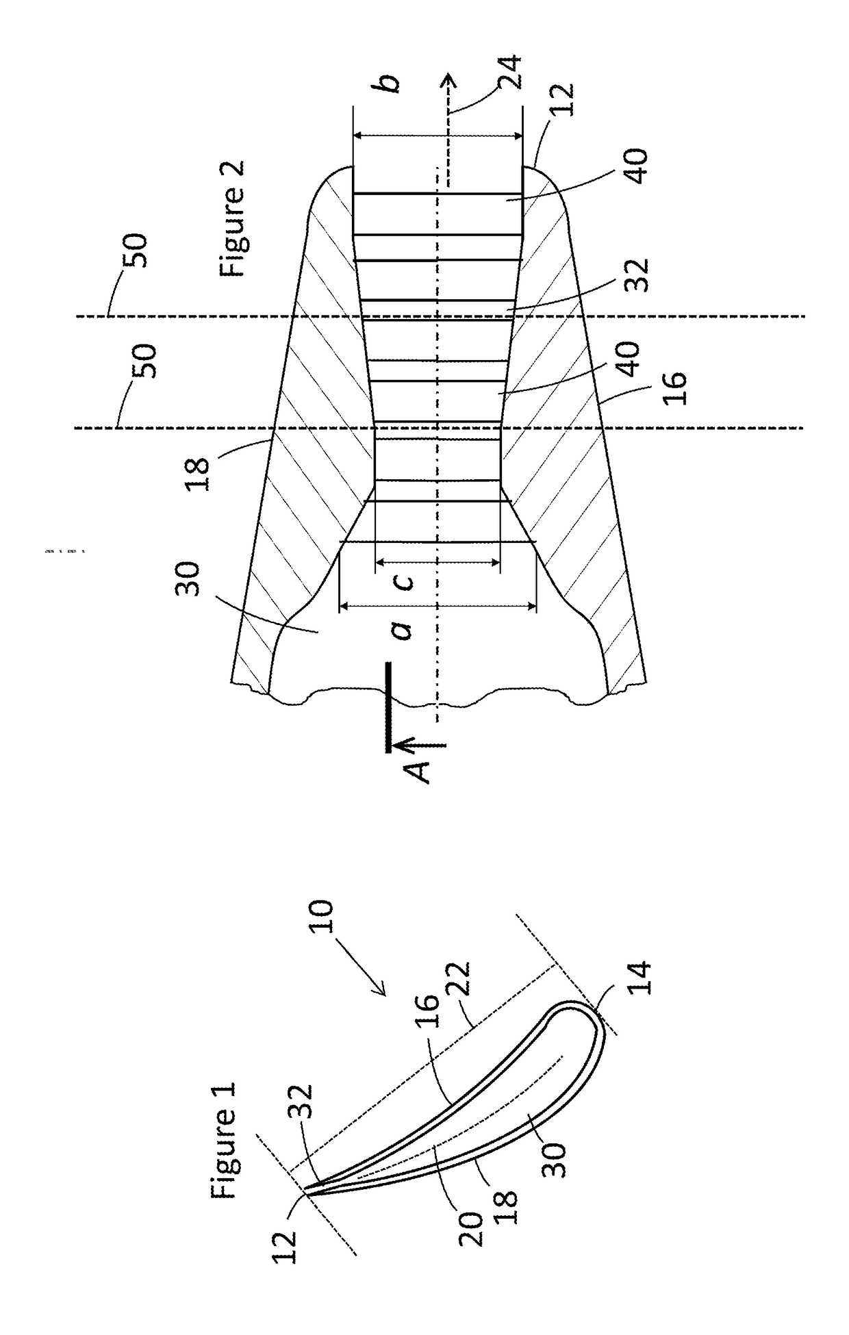
[0022]The blade described herein is a new blade designed for one type of gas turbine that is also designed so that it can be modified for use in another gas turbine by cutting back the trailing edge. This relatively radical solution allows a single blade design to be used in two or more different designs of gas turbine engine. For example, in one design of gas turbine engine the blade could be used ...


PUM


Abstract

A blade for a gas turbine is described, the blade comprising a trailing edge and a trailing edge cooling channel extending from a first upstream end to a second downstream end, in which the width of the trailing edge cooling channel in the direction perpendicular to the camber line of the blade varies and the narrowest width in the trailing edge cooling channel is at the first upstream end, so as to provide a blade where the trailing edge can be removed with a minimal change or no change in the cooling flow capacity through the trailing edge cooling channel. Related methods are also described.

Description

TECHNICAL FIELD[0001]The present disclosure relates to a gas turbine blade, and particularly to a gas turbine blade with a trailing edge cooling channel.BACKGROUND[0002]Gas turbine blades in modern gas turbine engines are extremely complicated and include various aerodynamic and cooling features. Design and testing of new blades typically takes years and considerable amounts of money. Considering this, a new blade design approach and manufacture method have been developed that can allow for increased flexibility, resulting in a considerable reduction in manufacturing development effort and costs.BRIEF DESCRIPTION[0003]An aspect provides a blade for a gas turbine, the blade comprising a trailing edge and a trailing edge cooling channel extending from a first upstream end to a second downstream end, in which the width of the trailing edge cooling channel in the direction perpendicular to the camber line of the blade varies and the narrowest width in the trailing edge cooling channel i...

Claims


Application Information

Patent Timeline
IPC IPC(8): F01D5/18
CPCF01D5/18F05D2230/10F05D2240/304F01D5/141F01D5/147F05D2220/32F05D2230/51F05D2270/101F01D5/181F01D5/186F01D5/187F05D2230/80F05D2230/90F01D25/12F02C7/12
Inventor MOZHAROV, ALEXEYBAUER, ANDREASGRAF, DOMINIC
Owner GENERAL ELECTRIC TECH GMBH
Why Eureka
Try Eureka