Airbag for a vehicle occupant restraint system

a technology for occupant restraints and airbags, which is applied in the direction of vehicle components, pedestrian/occupant safety arrangements, vehicular safety arrangments, etc., can solve the problem of airbags having to be deflated, and achieve the effect of preventing unplanned leakage flow and being easy to manufactur

Inactive Publication Date: 2008-01-10
TRW AUTOMOTIVE GMBH
View PDF6 Cites 57 Cited by
  • Summary
  • Abstract
  • Description
  • Claims
  • Application Information

AI Technical Summary

Benefits of technology

[0012]A closure guide can be provided on the airbag wall, said closure guide guiding said closure at least in sections along the airbag wall. The closure guide is most advantageously provided in the area of the gas outlet opening so that the closure adjoins the airbag wall especially closely there, preferably lies tight against it. In this manner, an undesired leakage flow is largely prevented.
[0013]Most preferably, the closure guide is arranged inside the airbag and is attached to the airbag wall. First of all, this means that no opening is needed in the airbag wall through which the control strap or the closure has to pass to the outside. Secondly, the control strap, the closure and the closure guide are located inside the airbag and are thus largely protected against external influences that could impair the function of these components.
[0014]In another embodiment, an unfolding force acting on the airbag wall and being oriented radially outwards with respect to the inflated airbag is greater at an attachment point of the control strap to the airbag wall than it is at an attachment point of the closure to the airbag wall. This entails the advantage that, whenever possible, the airbag will form the predefined first outer contour with the greatest possible airbag depth. If this airbag depth is not reached or if it is reduced due to external influences, the unfolding force at the attachment point between the closure and the airbag wall is still sufficient to keep the closure and the control strap under tension and to move them.
[0015]The wall section being turned to one of inside or outside can be configured as a bladder-like projection of the airbag wall. Such a projection is simple to manufacture and can be folded especially well to the inside or to the outside relative to the inflated airbag. Moreover, the unfolding force at the attachment site between the closure and the control strap can be established very well by making minimal changes to the bladder-like projection.

Problems solved by technology

As mentioned above, in one embodiment of the airbag, at a very large airbag depth in the first outer contour, it can be concluded that the vehicle occupant restraint system has deployed erroneously so that the airbag has to be deflated.

Method used


Image

  • Airbag for a vehicle occupant restraint system
  • Airbag for a vehicle occupant restraint system
  • Airbag for a vehicle occupant restraint system

Examples


Embodiment Construction

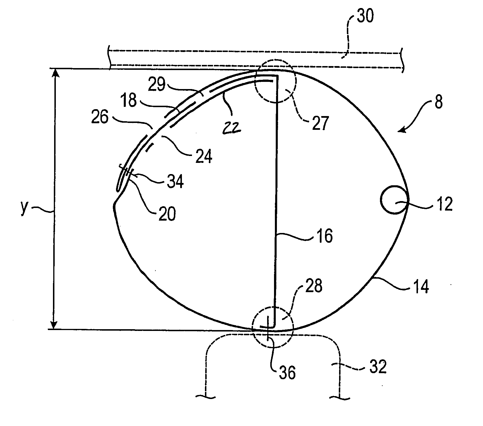
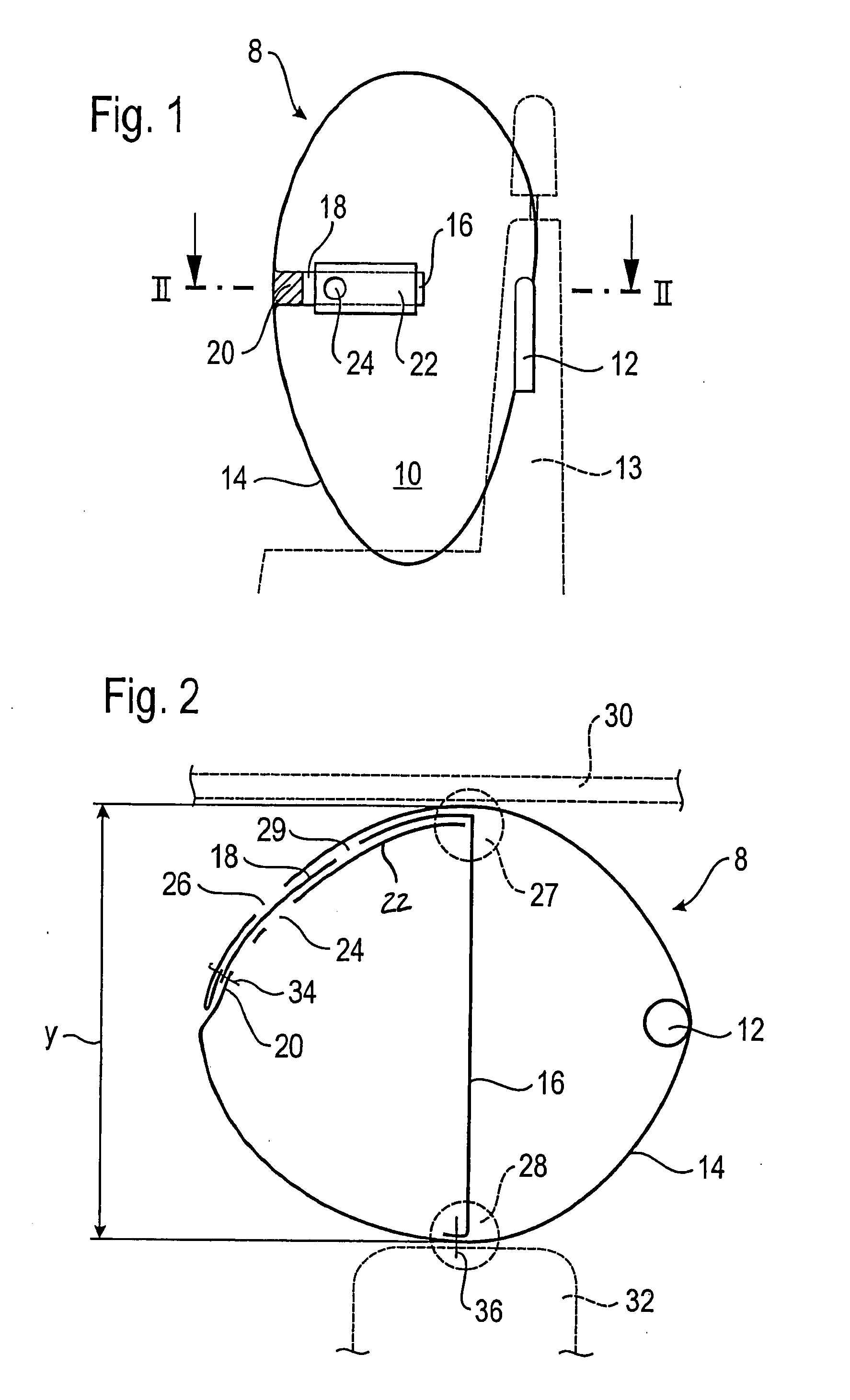
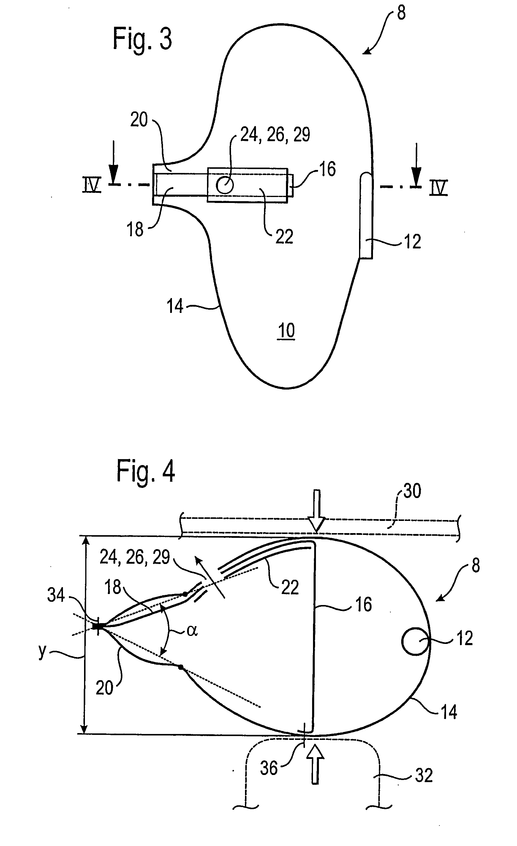
[0021]By way of example, FIG. 1 shows an airbag module 8 with an airbag 10 according to the invention and a gas generator 12. On the basis of the shape and positioning of the gas generator 12, it is clear that the depicted module is a side-impact airbag module that is preferably integrated into the backrest of a vehicle seat 13, although the invention is not limited to such modules. The figure shows a schematic vertical section through the gas generator 12 and through an airbag wall 14 of the airbag 10. Moreover, a control strap 16 has been cut approximately in the middle of the airbag 10, this control strap 16 extending perpendicular to the plane of projection through the interior of the airbag along an airbag depth y (see FIG. 2). The control strap 16 is connected to a closure 18 that extends to the left on the inner surface of the airbag wall 14, as shown in FIG. 1, and that is attached to a wall section 20 being turned or folded towards the interior of the inflated airbag 10 and...


PUM


Abstract

An airbag (10) for a vehicle occupant restraint system includes an airbag wall (14) having a gas outlet opening (26), and a control strap (16) extending through an interior of the airbag along an airbag depth (y) that is defined by a distance between two airbag wall areas (27, 28), the airbag wall areas (27, 28) being situated opposite to each other and the airbag wall areas (27, 28) being joined to one another by the control strap (16). A wall section (20) is turned one of inside and outside relative to the inflated airbag (10), depending on the airbag depth (y), such that, in response to a displacement of the control strap (16), the airbag (10) can be moved from a first outer contour, in which the airbag depth (y) is large and the wall section (20) is turned into the interior of the airbag, to a second outer contour, in which the airbag depth (y) is smaller and the wall section (20) is turned outside. The airbag (10) has a closure (18) for the gas outlet opening (26) that is joined, on the one hand, to the control strap (16) and, on the other hand, to the wall section (20). The closure (18) can be actively moved in opposite directions respectively by the control strap (16) and the wall section (20), in order to open and close the gas outlet opening (26) to one of a greater and lesser extent.

Description

TECHNICAL FIELD[0001]The invention relates to an airbag for a vehicle occupant restraint system, including an airbag wall having a gas outlet opening, and a control strap extending through an interior of the airbag along an airbag depth that is defined by a distance between two airbag wall areas that are situated opposite to each other and that are joined to one another by the control strap, a wall section being turned inside or outside relative to the inflated airbag, depending on the airbag depth.BACKGROUND OF THE INVENTION[0002]Such an airbag has already been disclosed in the generic German patent application DE 102 36 859 A1 in which the wall section that can be turned inside or outside is a tube-like wall section that has a gas outlet opening. A first end of the control strap is fastened to the tube-like wall section near the gas outlet opening and a second, opposite end of the control strap is attached to the airbag wall. The length of the control strap and the attachment poin...

Claims


Application Information

Patent Timeline
Patent Type & Authority Applications(United States)
IPC IPC(8): B60R21/16B60R21/2338
CPCB60R21/233B60R2021/23384B60R21/239B60R21/2338
Inventor FISCHER, ANTONHOFMANN, SVEN
Owner TRW AUTOMOTIVE GMBH
Why Eureka
Try Eureka