Pseudo-reflective read inhibitor for optical storage media

a technology of optical storage media and read inhibitor, which is applied in the field of optical media, can solve the problems of low cost copies of their material that will have a long lifetime, high cost of cds and dvds, and high cost of purchasing them

Inactive Publication Date: 2005-01-04
FLEXPLAY TECH INC
View PDF7 Cites 60 Cited by
  • Summary
  • Abstract
  • Description
  • Claims
  • Application Information

AI Technical Summary

Benefits of technology

A goal of the invention is to simultaneously satisfy the above-discussed requirements of low cost, limited content lifetime, avoidance of rental returns and minimum changes to existing manufacturing precesses which, in the case of the prior art, are not simultaneously satisfied.

Problems solved by technology

Unfortunately, the purchase of CDs and DVDs can be expensive.
The cost is associated not primarily with the manufacturing cost of the optical disks, but with the value of the information, such as movies or software, encoded on the disks.
Content providers, such as movie studios or software companies, do not want to sell at a low cost copies of their material that will have a long lifetime in the marketplace.
Rentals of CDs and DVDs enable consumers to access the information at a lower cost, but the need to return the rentals on time is inconvenient.
Heretofore, the requirements of low cost, limited content lifetime, avoidance of rental returns and minimum changes to existing manufacturing precesses referred to above have not been fully met.

Method used


Image

  • Pseudo-reflective read inhibitor for optical storage media
  • Pseudo-reflective read inhibitor for optical storage media
  • Pseudo-reflective read inhibitor for optical storage media

Examples


example 1

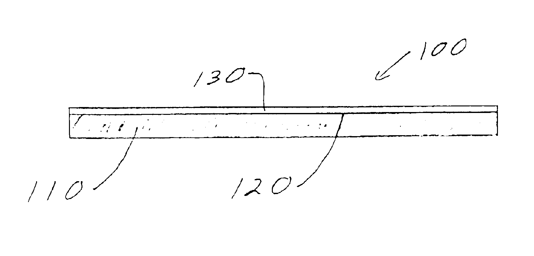
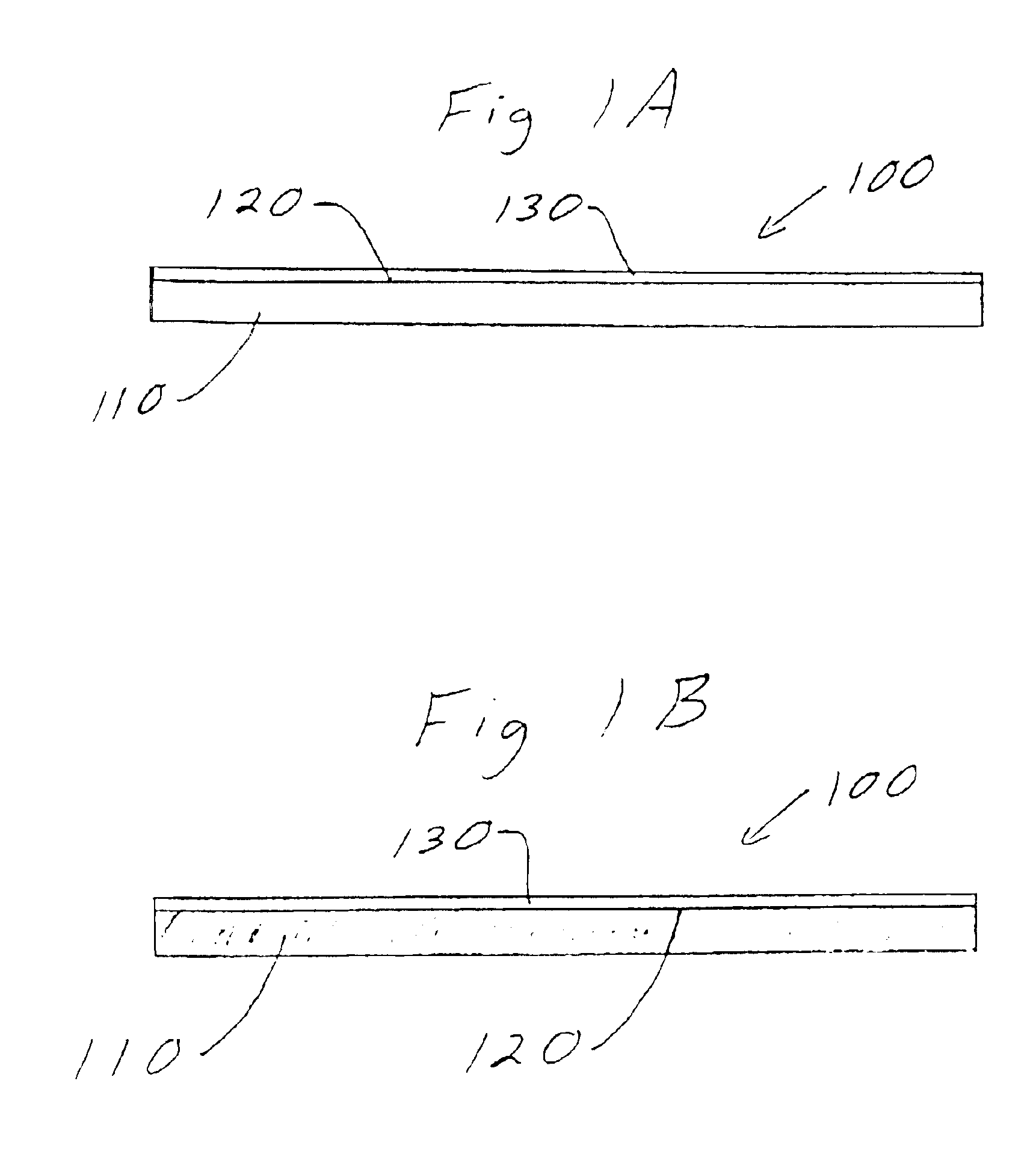
Referring to FIGS. 1a-1b, edge views of an optical disk 100 with a pseudo-transmissive read inhibitor are shown. The optical disk 100 includes a substrate 110, a reflective layer 120 and a lacquer layer 130. FIG. 1a shows the optical disk 100 in a first state wherein the substrate 110 is substantially optically transmissive. FIG. 1b shows the optical disk 100 in a second state wherein the substrate is substantially optically non-transmissive. The transformation from the first state to the second state is at-least-in-part a function of time from an initializing event, in this particular example, the opening of a substantially gas impermeable membrane (not shown) that encloses the optical disk 100 while it is packed, shipped and sold.

example 2

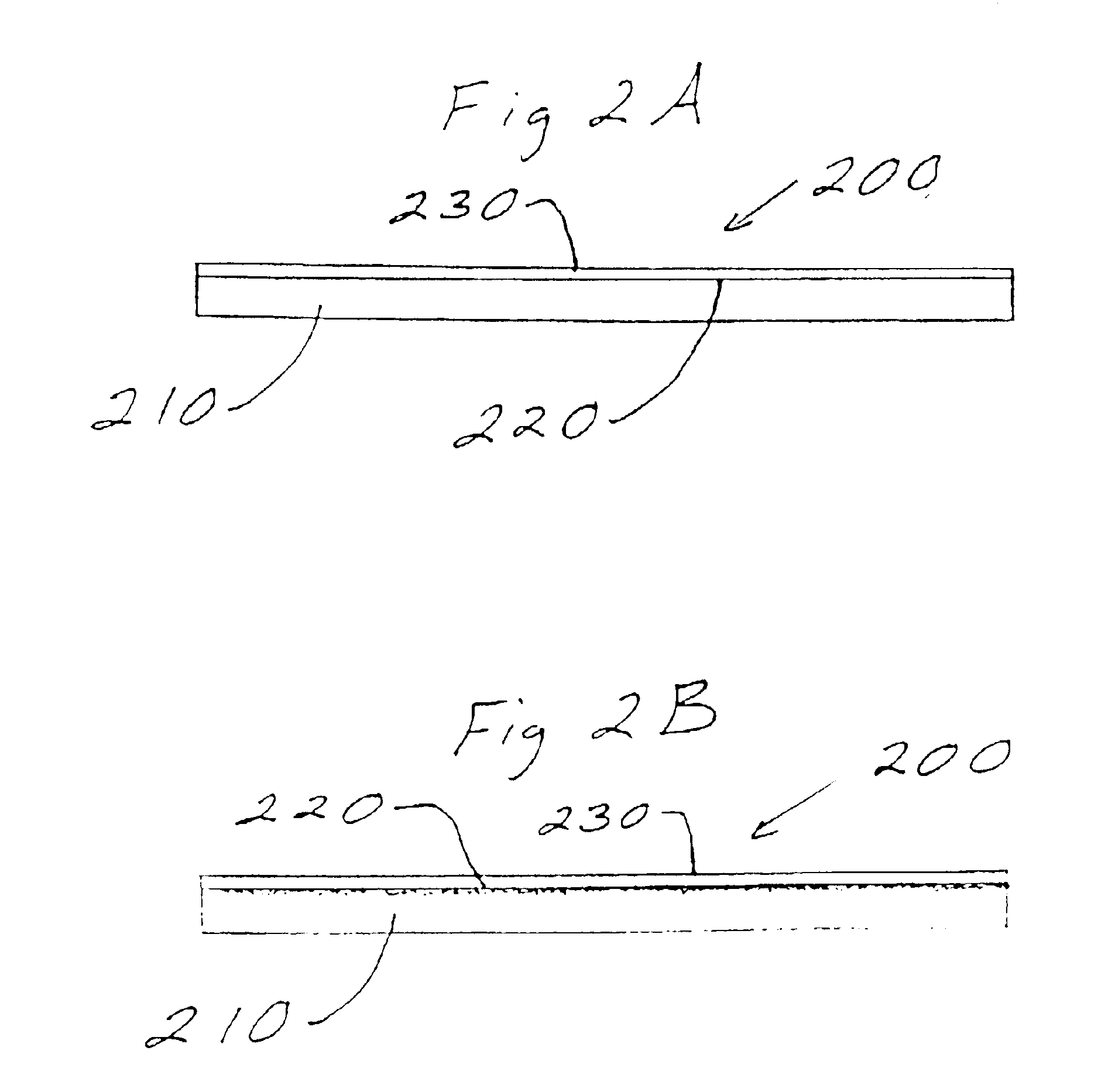
Referring to FIGS. 2a-2b, edge views of an optical disk 200 with a pseudo-reflective read inhibitor are shown. The optical disk 200 includes a substrate 210, a data encoded component 220 and a lacquer layer 230. In this example, the data encoded component 220 is a thin film of metal. FIG. 1a shows the optical disk 200 in a first state wherein the data encoded component 220 is substantially optically reflective. FIG. 1b shows the optical disk 200 in a second state wherein the data encoded component 220 is substantially optically non-reflective. As in the first example, the transformation from the first state to the second state is at-least-in-part a function of time from an initializing event, in this second example, the opening of a substantially air tight laminated polymeric container (not shown) that encloses the optical disk 200 while it is packed, shipped and sold.

Practical Applications of the Invention

A practical application of the invention that has value within the technologi...


PUM

PropertyMeasurementUnit
timeaaaaaaaaaa
timeaaaaaaaaaa
timeaaaaaaaaaa

Abstract

System and methods are described for inhibiting the readability of an optical media due to changes in a pseudo-reflective material that composes the optical media after the optical media has been exposed to air for a predetermined time. An optical media includes a data encoded component. At least a fraction of the data encoded component transforms from a substantially optically reflective state to a substantially optically non-reflective state as at-least-in-part a function of time from an initializing event. The systems and methods provide advantages because of low cost, limited content lifetime, avoidance of rental returns and minimum changes to existing manufacturing processes.

Description

BACKGROUND OF THE INVENTION1. Field of the InventionThe invention relates generally to the field of optical media. More particularly, the invention relates to time sensitive disposable optical media.2. Discussion of the Related ArtOptical disks such as CDs and DVDs are sold and rented to consumers for use at home. The content of the optical disks may be music, movies, software or data. Unfortunately, the purchase of CDs and DVDs can be expensive. The cost is associated not primarily with the manufacturing cost of the optical disks, but with the value of the information, such as movies or software, encoded on the disks. Content providers, such as movie studios or software companies, do not want to sell at a low cost copies of their material that will have a long lifetime in the marketplace. Rentals of CDs and DVDs enable consumers to access the information at a lower cost, but the need to return the rentals on time is inconvenient. It would be desirable to have an optical media (e.g....

Claims


Application Information

Patent Timeline
Patent Type & Authority Patents(United States)
IPC IPC(8): G11B23/28G11B7/0037G11B7/24G11B7/253G11B7/00G11B7/258G11B7/005G11B11/00
CPCG11B7/0037G11B7/0052G11B7/252G11B7/253G11B7/2542G11B23/0021G11B23/282G11B7/258G11B7/2534Y10T428/21G11B7/2585G11B7/259G11B7/2595
Inventor BAKOS, YANNISBRYNJOLFSSON, ERIKHELLER, ADAMHELLER, EPHRAIM
Owner FLEXPLAY TECH INC
Why Eureka
Try Eureka