Methanol production method and methanol production apparatus

a technology of methanol and production method, which is applied in the direction of physical/chemical process catalysts, bulk chemical production, metal/metal-oxide/metal-hydroxide catalysts, etc., can solve the problems of overheating of the catalyst bed, excessive reaction, and excessive reaction, so as to reduce the amount of energy used, reduce the circulation ratio, and high carbon yield

Active Publication Date: 2017-08-24
MITSUBISHI GAS CHEM CO INC
View PDF3 Cites 4 Cited by
  • Summary
  • Abstract
  • Description
  • Claims
  • Application Information

AI Technical Summary

Benefits of technology

[0026]According to the present invention, it is possible to provide a method for producing methanol and an apparatus for producing methanol in each of which in the synthesis of methanol, the temperature of the catalyst layer is allowed to keep within an appropriate temperature range, the amount of energy used is reduced by reducing the circulation ratio, moreover a high carbon yield is achieved, and additionally the deviations of the loads on the respective catalyst layers are reduced.

Problems solved by technology

Patent Document 1 has pointed out a problem that in the methanol synthesis at a low circulation ratio, the reactant partial pressure of the gas is sometimes high, and this causes excessive reaction and the occurrence of overheating of the catalyst bed.
Patent Document 3 discloses that higher partial pressures of reactants in reactors can lead to excessive reaction and high temperatures.

Method used


Image

  • Methanol production method and methanol production apparatus
  • Methanol production method and methanol production apparatus
  • Methanol production method and methanol production apparatus

Examples


example 1

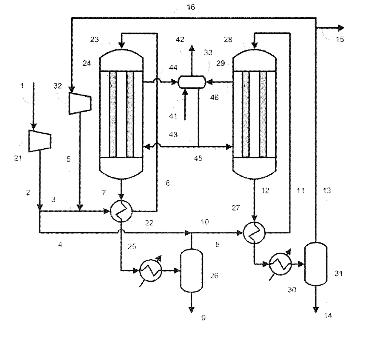
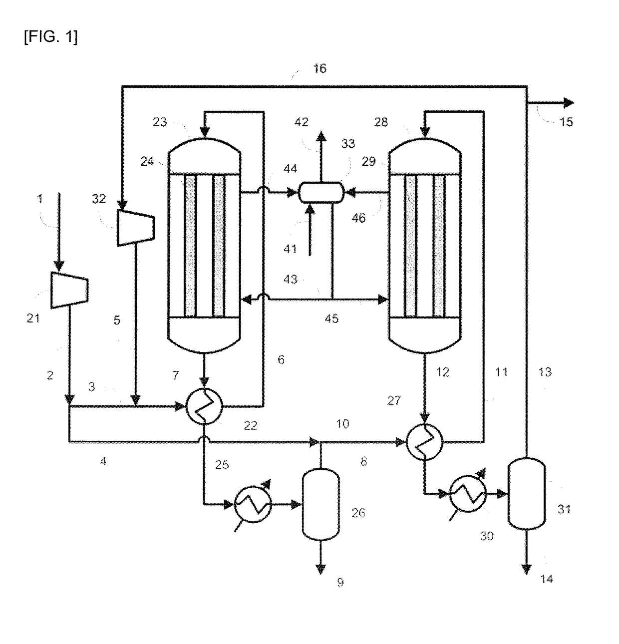
[0094]In Example 1, the production apparatus shown in FIG. 1 was used. The involved conditions were as follows. Specifically, as the raw material gas, the gas produced by the steam-reforming reaction of natural gas was used, and the synthesis of methanol was performed under the condition of a circulation ratio of 1.0. As the catalysts in the reactors 23 and 28, the methanol synthesis catalyst C was used. The pressure was increased to 9.9 MPa-G (101 kg / cm2-G) with the compressor 21. In a line 3, 40 mol % of the synthesis raw material gas (make-up gas) increased in pressure was allowed to flow, and subjected to the heat exchange with the outlet gas (reaction mixture) including the reaction product flowing in the line 7 of the outlet of the reactor 23, and thus preheated so as for the temperature in the line 6 to be 200° C. The residual make-up gas, namely, 60 mol % of the make-up gas was allowed to flow in the line 4. As the reactor 23, a reactor having the inner tubes 24 made of a ca...

example 2

[0110]In Example 2, the production apparatus shown in FIG. 1 was used. The involved conditions were as follows. Specifically, the raw material gas was adjusted to have the same composition as the composition of the raw material gas used in Example 1, and the synthesis of methanol was performed under the condition of the circulation ratio of 1.1. Additionally, 50 mol % of the make-up gas was allowed to flow in the line 3, and the residual make-up gas, namely, 50 mol % of the make-up gas was allowed to flow in the line 4. The amount of the purge gas extracted from the line 15 to outside the system was regulated so as for the circulation ratio to be 1.1. The pressure increased with the compressor 21 and the temperatures in the line 6 and the line 11 were set to be the same as in Example 1. A carbon steel was used for the materials of the inner tubes 24 of the reactor 23 and the inner tubes 29 of the reactor 28, and the methanol synthesis catalyst C was filled in the reactor 23 and the ...

example 3

[0120]In Example 3, the production apparatus shown in FIG. 1 was used. The involved conditions were as follows. Specifically, the raw material gas was regulated to have the same composition as the composition of the raw material gas used in Example 1, and the synthesis of methanol was performed under the condition of the circulation ratio of 0.8.

[0121]Additionally, 40 mol % of the make-up gas was allowed to flow in the line 3, and the residual make-up gas, namely, 60 mol % of the make-up gas was allowed to flow in the line 4. The outlet gas from the first synthesis step was cooled to 80° C. with the condenser 25 to promote the condensation of methanol. The amount of the purge gas extracted from the line 15 to outside the system was regulated so as for the circulation ratio to be 0.8. The pressure increased with the compressor 21 and the temperatures in the line 6 and the line 11 were also set to be the same as in Example 1. A carbon steel was used for the materials of the inner tube...


PUM

PropertyMeasurementUnit
mol %aaaaaaaaaa
mol %aaaaaaaaaa
temperatureaaaaaaaaaa

Abstract

Synthesizing methanol from a synthesis gas and separating an unreacted gas from a reaction mixture obtained by passing through the synthesis step, the method including a synthesis loop having at least two synthesis steps and at least two separation steps; obtaining a first mixed gas by increasing through a circulator a pressure of a residual gas, obtained by removing a purge gas from the final unreacted gas separated from the final reaction mixture subsequent to the final synthesis step, and by mixing the residual gas with a fraction of a make-up gas; synthesizing methanol; separating a first unreacted gas from the first reaction mixture obtained in the synthesizing step; obtaining a second mixed gas by mixing the first unreacted gas and a fraction of the make-up gas; finally synthesizing methanol; and separating the final unreacted gas from the final reaction mixture obtained in the final synthesis step.

Description

TECHNICAL FIELD[0001]The present invention relates to a method for producing methanol and an apparatus for producing methanol.BACKGROUND ART[0002]Industrial production of methanol is performed by using a fossil fuel as a feedstock, and by allowing a synthesis gas (hereinafter, also referred to as a “synthesis raw material gas” or “raw material gas”) mainly comprising carbon monoxide, carbon dioxide and hydrogen, obtained by reforming the fossil fuel, to react on a catalyst. The involved reaction conditions are such that the pressure is 50 to 150 kg / cm2, the temperature is 160 to 300° C., and the catalyst used is a catalyst mainly comprising copper / zinc. The methanol synthesis reaction is represented by the following formulas (1) and (2).[Formula 1]CO+2H2→CH3OH  (1)CO2+3H2→CH3OH+H2O  (2)[0003]Patent Document 1 has pointed out a problem that in the methanol synthesis at a low circulation ratio, the reactant partial pressure of the gas is sometimes high, and this causes excessive react...

Claims


Application Information

Patent Timeline
Patent Type & Authority Applications(United States)
IPC IPC(8): C07C29/152B01J8/04
CPCC07C29/152B01J8/0492B01J2208/00893B01J2208/00106B01J8/0496B01J37/03B01J23/80B01J37/00C07C31/04C07B61/00Y02P20/52
Inventor KAMBE, YASUAKIUCHIDA, KOHEIWATANABE, HIROSHIHIRAKAWA, DAIGOHASEGAWA, TATSUYA
Owner MITSUBISHI GAS CHEM CO INC
Why Eureka
Try Eureka