Tree Stand Blind

a blind and tree stand technology, applied in the field of hunting blinds, can solve the problems of difficult access to the tree stand, no camouflage to break up the outline or silhouette, and the tree stand offers, and achieve the effect of preventing it from flapping in the wind

Active Publication Date: 2017-10-19
BOREN WILLIAM CHARLES
View PDF7 Cites 3 Cited by
  • Summary
  • Abstract
  • Description
  • Claims
  • Application Information

AI Technical Summary

Benefits of technology

[0013]When the blind is anchored in place, the rigid support holds the fabric of the bottom portion of the blind away from a user's knees. If needed, a user may then tighten the drawstrings to make the blind more rigid and to prevent it from flapping in the wind.
[0014]When assembled in this manner, the blind has no roof and has no upper front wall. This allows a user to stand up and shoot a firearm or bow in any direction, including directly under the blind or directly above the blind. The bottom platform of a tree stand and the bottom portion of the blind function as a “floor” that helps hide the user from game animals below the blind. The sides of the blind break up the user's silhouette and help hide the user and the tree stand from game animals that are not directly under the blind. An optional canopy may be fitted to the blind to protect the user from rain. The user may wear a camouflage bib and facemask that match the camouflage pattern of the blind—by doing so, the user effectively “becomes the blind” and the user's clothing functions as the upper front wall of the blind.

Problems solved by technology

However, tree stands do offer some disadvantages.
The stands typically have no camouflage to break up the outline or silhouette of the stand and the hunter.
One way hunters avoid detection is to climb higher in a tree, but this practice can be dangerous and can make it difficult to access the tree stand.
This method of concealment is disadvantageous because it can be tedious to install, limits a hunter's vision, and limits the hunter's ability to aim their firearm or bow at game animals.
Other prior art blinds—such as the blind disclosed in U.S. Pat. No. 7,559,334—are better adapted to fit a tree stand but are still disadvantageous because they limit a user's ability to see out of the blind and still limit the user's ability to take aim at game animals that are on the move like game birds flying overhead.

Method used


Image

  • Tree Stand Blind
  • Tree Stand Blind
  • Tree Stand Blind

Examples


Embodiment Construction

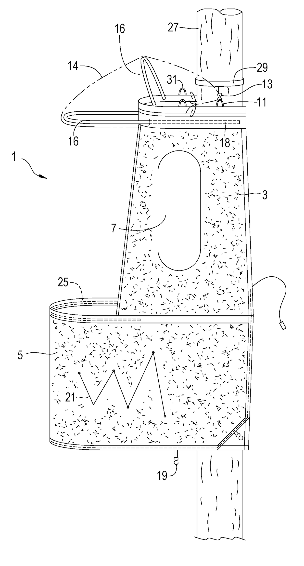
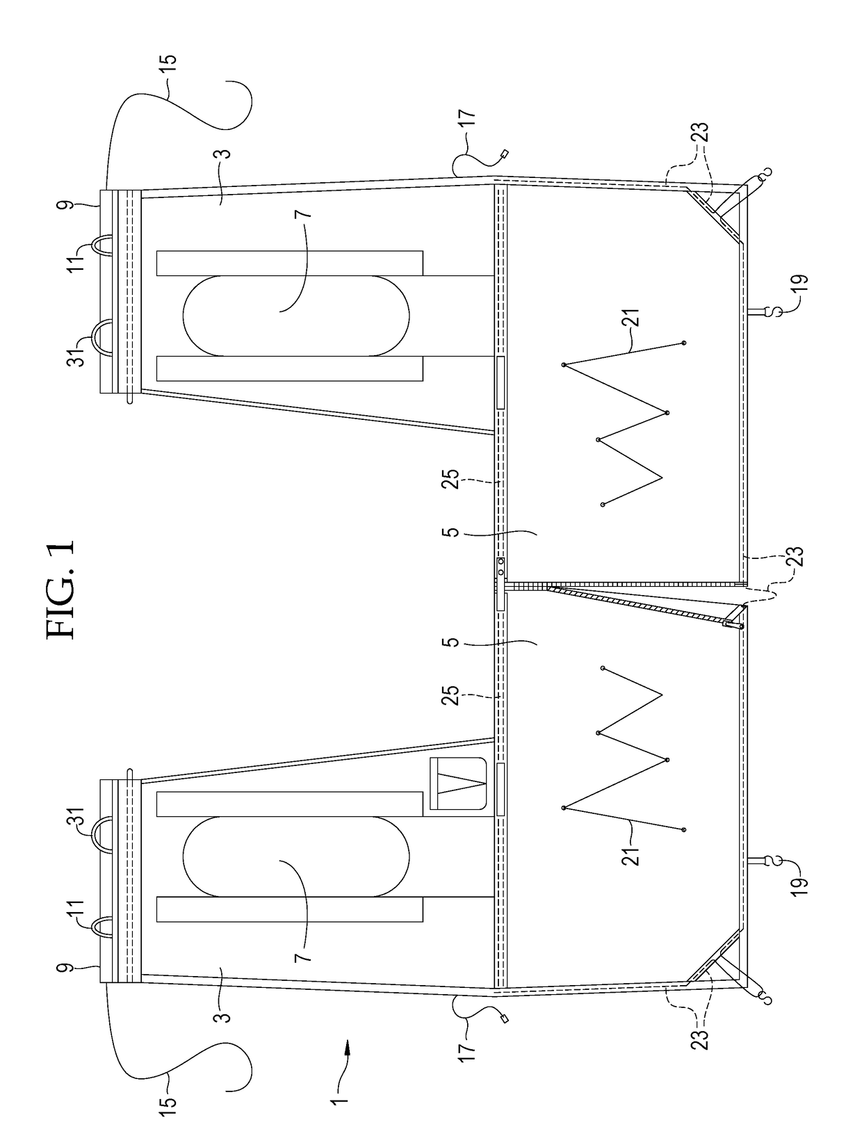
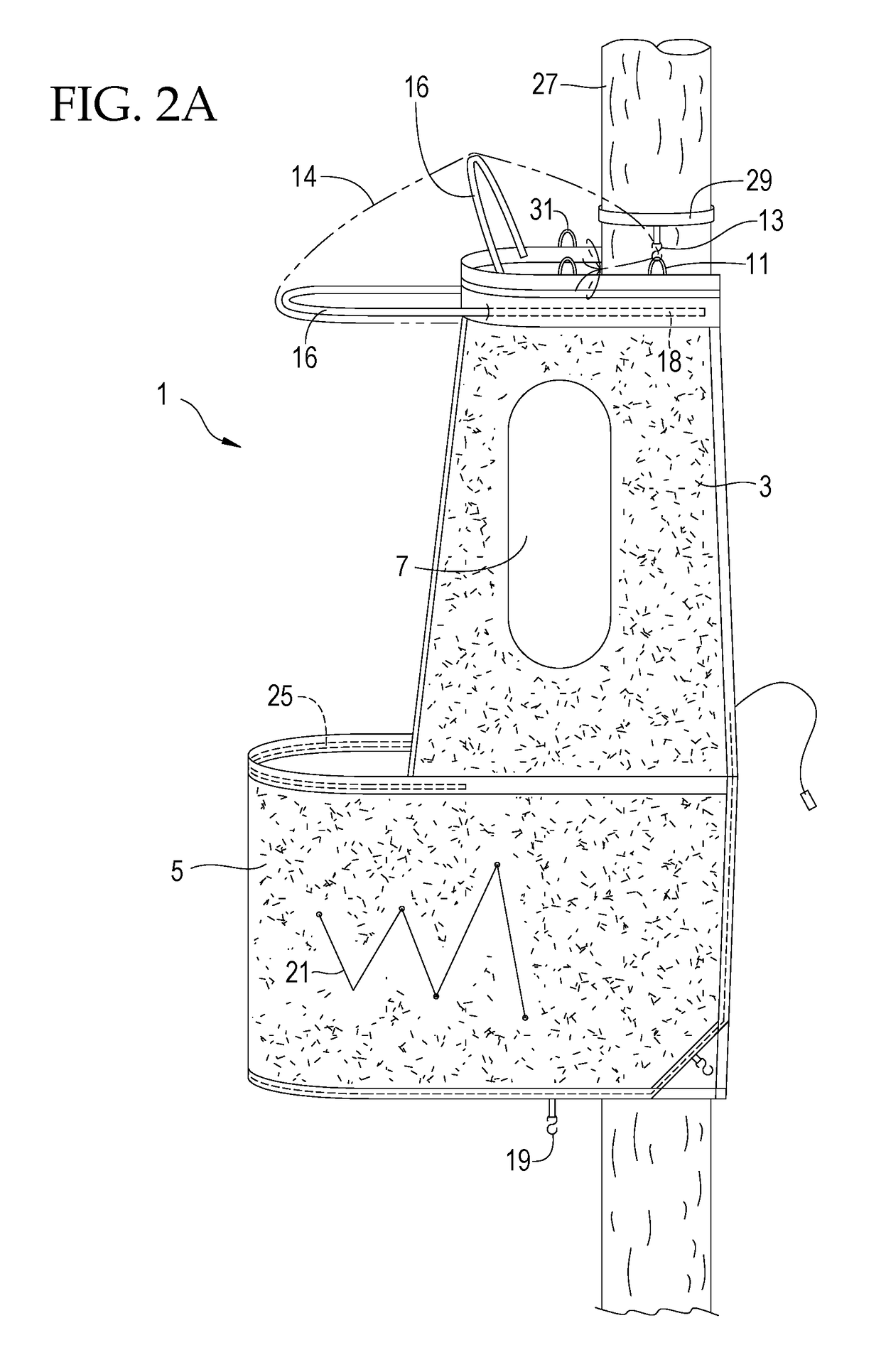
[0030]FIG. 1 depicts a tree stand blind 1 that is spread out on a flat surface. The blind 1 is comprised of two sides 3 connected by a lower center portion 5. The blind 1 may be made of flexible material, including a suitable fabric which may include a camouflage pattern to hide the user. For clarity, the figures are depicted in black and white. The blind 1 does not have a roof and does not have a complete front wall. Each side 3 of the blind incorporates a window 7. The windows 7 include a moveable shade mechanism that allows them to be fully or partially opened or closed as needed by the user. The top 9 of each of the sides 3 incorporates a rigid support section that may be formed by a sleeved fiberglass rod or other suitable material.

[0031]One or more support loops 11 are attached to the tops 9 of each side 3. The support loops 11 may be hung on hooks 13 (not depicted in FIG. 1) to suspend the blind 1 from a tree. The hooks 13 may be affixed to a tree strap (not shown) that is at...


PUM


Abstract

A tree stand hunting blind is comprised of two sides connected by a lower center portion. The blind does not have a roof and does not have a complete front wall. This allows a user to stand up and shoot a firearm or bow in any direction, including directly under the blind or directly above the blind. The bottom platform of a tree stand and the bottom portion of the blind function as a “floor” that helps hide the user from game animals below the blind. The sides of the blind break up the user's silhouette and help hide the user and the tree stand from game animals that are not directly under the blind. Each side of the blind incorporates a window with a moveable shade mechanism that allows them to be fully or partially opened or closed as needed by the user.

Description

PRIORITY[0001]This application claims the Apr. 19, 2016 priority date of U.S. Provisional Patent Application Ser. No. 62 / 324,845. The entirety of that provisional application is incorporated herein by reference.FIELD OF THE DISCLOSURE[0002]The present invention relates to hunting blinds adapted for use with tree stands.BACKGROUND OF THE INVENTION[0003]Hunters commonly hunt from elevated tree stands. The tree stands help hunters to remain hidden from game and give the hunter a greater field of view. Ladder stands are one type of tree stands. Climbing stands and lock-on stands are other common types of tree stands.[0004]However, tree stands do offer some disadvantages. The stands typically have no camouflage to break up the outline or silhouette of the stand and the hunter. A hunter in the stand is easily visible to game animals which are close to the stand and look up, and the hunter is in the line of sight of animals that are far from the stand. Game animals can easily detect moveme...

Claims


Application Information

Patent Timeline
Patent Type & Authority Applications(United States)
IPC IPC(8): A01M31/02E04H15/58E04H15/48E04H15/00E04H15/32E04H15/04E04H15/64E04H15/54
CPCA01M31/025E04H15/001E04H15/04E04H15/48E04H15/54E04H15/64E04H15/322E04H15/58
Inventor BOREN, WILLIAM CHARLES
Owner BOREN WILLIAM CHARLES
Why Eureka
Try Eureka