
Air monitoring device

A technology of air monitoring and collecting boxes, which is applied in the direction of measuring devices, circuit devices, battery circuit devices, etc., can solve the problems such as the inconvenience of dust cleaning, and achieve the effect of solving the inconvenience of cleaning and power supply

Inactive Publication Date: 2021-06-25
韩美群
View PDF11 Cites 1 Cited by
  • Summary
  • Abstract
  • Description
  • Claims
  • Application Information

AI Technical Summary

Problems solved by technology

[0004] In order to make up for the above deficiencies, the present invention provides an air monitoring device, which aims to improve the problem of inconvenient dust cleaning

Method used


Image

  • Air monitoring device
  • Air monitoring device
  • Air monitoring device

Examples


Embodiment 1

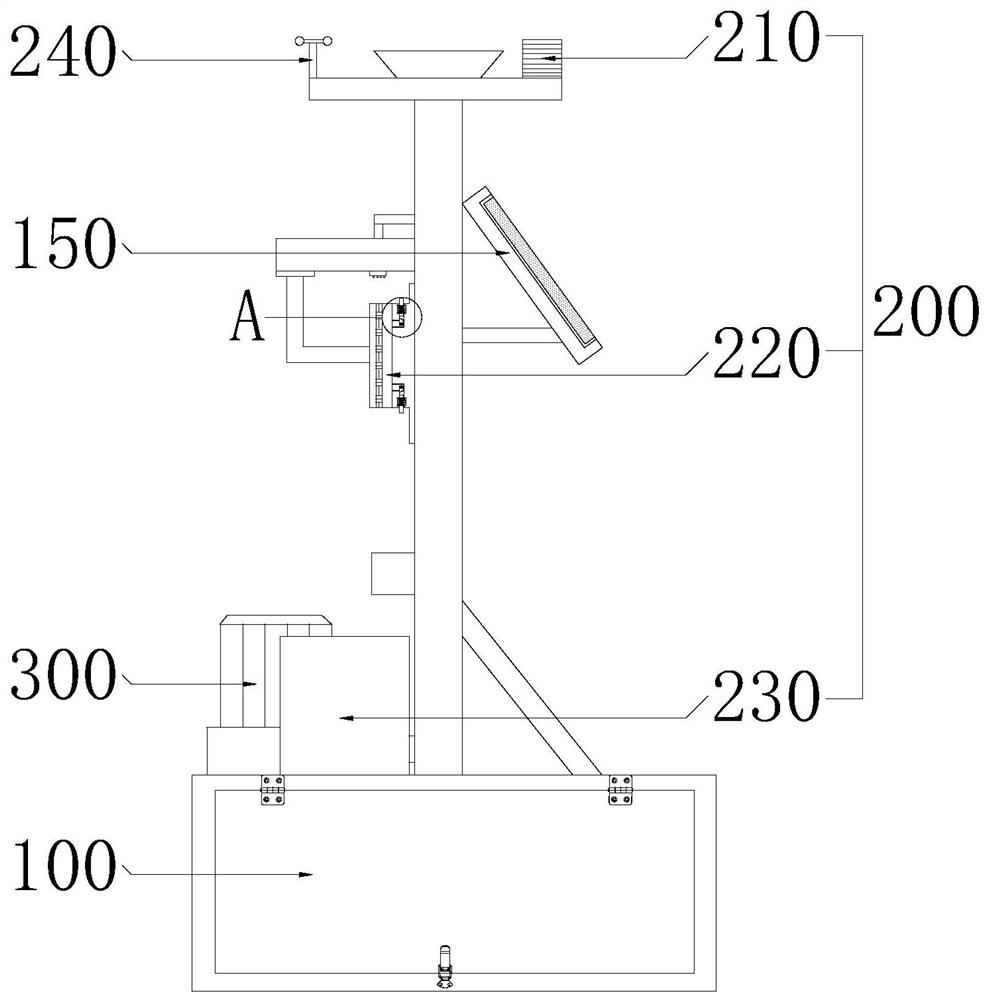
[0037] see figure 1 , the present invention provides a technical solution: an air monitoring device, including a fixed collection assembly 100 , a device body 200 and a cleaning assembly 300 .

[0038] Wherein, the fixed collection component 100 plays a role of fixing the device body 200 and collecting rainwater, and the cleaning component 300 plays a role of cleaning the device body 200 .

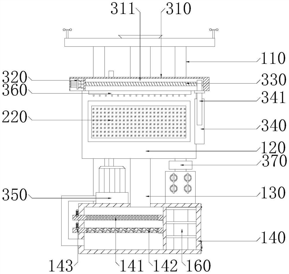
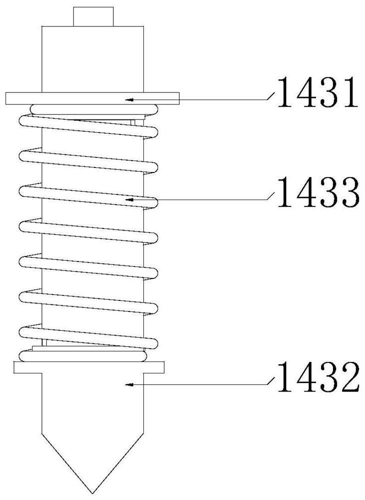
[0039] see figure 1 , figure 2 , image 3 and Figure 4 , the fixed collection assembly 100 includes a fixed frame 110, a fixed plate 120, a collection pipe 130, a collection box 140, a solar photovoltaic panel 150 and a battery pack 160, and the fixed plate 120 is fixedly installed on the fixed frame 110. It should be noted that the fixed plate 120 Fixing with bolts, the fixing plate 120 is provided with a second fixing groove 121 and an elastic button 122, and the elastic button 122 is arranged in the second fixing groove 121. In the specific setting, the setting of the second fixin...

Embodiment 2

[0045] see figure 1 , the present invention provides a technical solution: an air monitoring device, including a fixed collection assembly 100 , a device body 200 and a cleaning assembly 300 .

[0046] Wherein, the fixed collection component 100 plays a role of fixing the device body 200 and collecting rainwater, and the cleaning component 300 plays a role of cleaning the device body 200 .

[0047] see figure 1 , figure 2 , image 3 and Figure 4 , the fixed collection assembly 100 includes a fixed frame 110, a fixed plate 120, a collection pipe 130, a collection box 140, a solar photovoltaic panel 150 and a battery pack 160, and the fixed plate 120 is fixedly installed on the fixed frame 110. It should be noted that the fixed plate 120 Fixing with bolts, the fixing plate 120 is provided with a second fixing groove 121 and an elastic button 122, and the elastic button 122 is arranged in the second fixing groove 121. In the specific setting, the setting of the second fixin...


PUM


Abstract

The invention provides an air monitoring device, and belongs to the technical field of air monitoring. The air monitoring device comprises a fixed collecting assembly, an equipment body and a cleaning assembly, wherein the fixed collecting assembly comprises a fixing frame, a fixing plate, a collecting pipe, a collecting box, a solar photovoltaic panel and a storage battery pack. According to the invention, through arrangement of the collecting pipe and the collecting box, the collecting pipe is arranged on the fixing plate, the collecting box is arranged below the fixing frame, and the collecting pipe communicates with the collecting box, so that rainwater can be collected, and the problem that water is difficult to use for cleaning equipment is solved; through the arrangement of the cleaning assembly, the cleaning assembly comprises a baffle, a motor, a threaded rod, a sponge, a water pump and a spray head, wherein rainwater collected in the collecting box can be pumped through the water pump and sprayed to equipment through the spray head, and the display screen can be wiped through the motor, the threaded rod and the sponge, so that the equipment is cleaned; and through the arrangement, the problem that the equipment is inconvenient to clean can be solved.

Description

technical field [0001] The invention relates to the technical field of air monitoring, in particular to an air monitoring device. Background technique [0002] Monitoring refers to fixed-point, continuous or regular sampling and measurement of pollutants in the air. In order to monitor the air, generally several air monitoring points are set up in a city, and automatic monitoring instruments are installed for continuous automatic monitoring and analysis. and obtain relevant data. [0003] At present, because the air monitoring device is installed outdoors, a large amount of dust will accumulate on the surface of the protective film of the display after long-term use. The existing device lacks the function of cleaning dust. At the same time, due to the inconvenience of getting water outdoors, it will cause certain difficulties in cleaning. Contents of the invention [0004] In order to make up for the above deficiencies, the present invention provides an air monitoring dev...

Claims


Application Information

Patent Timeline
Patent Type & Authority Applications(China)
IPC IPC(8): G01D21/02G01D11/00G01D11/30B08B3/02H02J7/35
CPCG01D21/02G01D11/00G01D11/30B08B3/02H02J7/35
Inventor 韩美群
Owner 韩美群
Learn More