Vent box

Inactive Publication Date: 2015-04-09
GE OIL & GAS ESP
View PDF17 Cites 0 Cited by
  • Summary
  • Abstract
  • Description
  • Claims
  • Application Information

AI Technical Summary

Benefits of technology

[0004]In a preferred embodiment, the present invention includes a vent box for venting gas present on a power cable. The vent box includes an interior and one or more cable clamps disposed through the vent box into the interior to allow for the cable to be connected to the vent box. The vent box also includes a bottom with a plurality of vents disposed therein, and at least two s

Problems solved by technology

These prior art vent boxes have failed to meet regulatory requir

Method used


Image

  • Vent box
  • Vent box
  • Vent box

Examples


Embodiment Construction

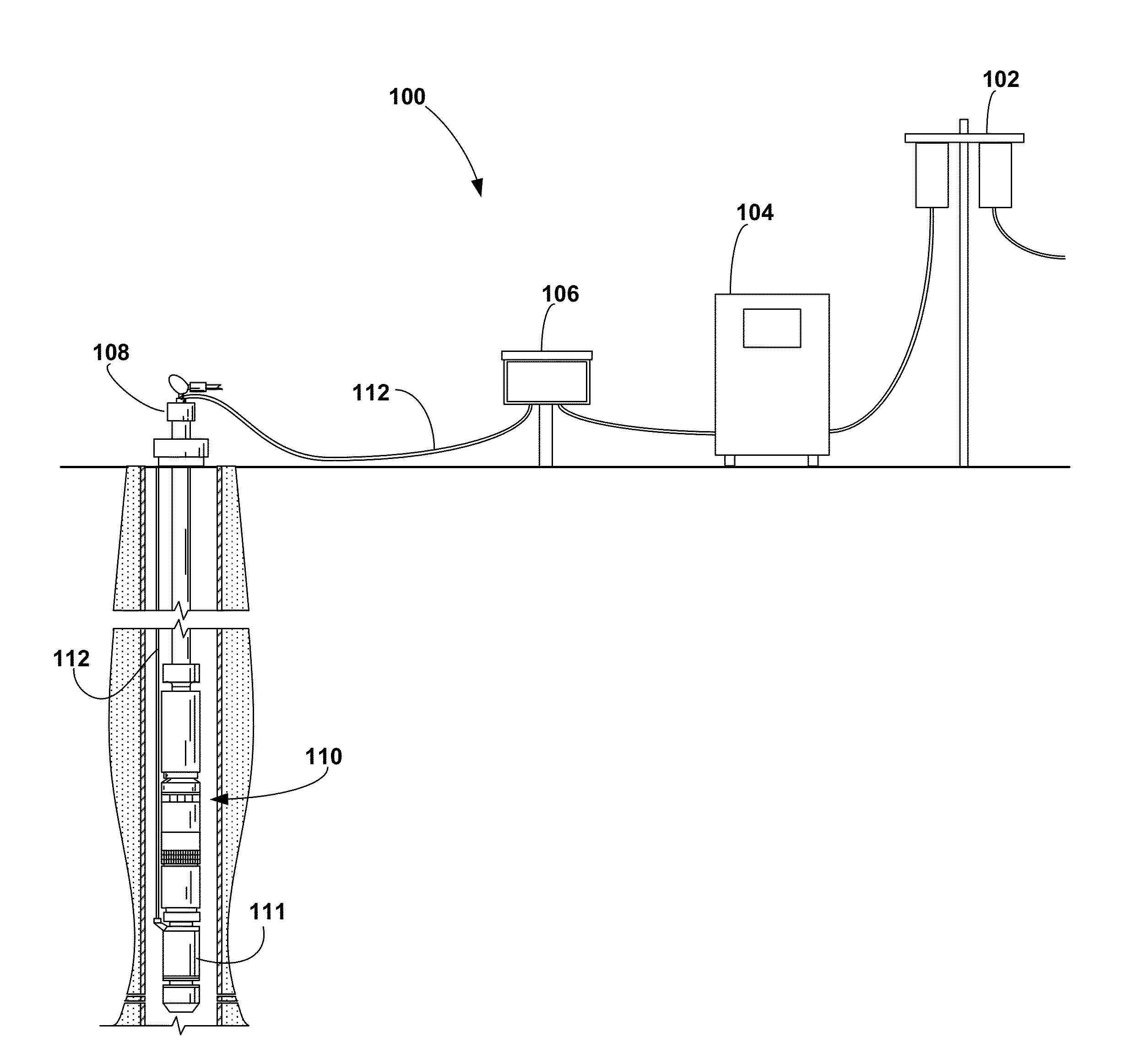
[0012]In accordance with a preferred embodiment of the present invention, FIG. 1 shows a side perspective view of a downhole pumping system 100. The downhole pumping system 100 includes one or more transformers 102, a power supply 104, a vent box 106, a wellhead 108, and a downhole pumping system 110. The downhole pumping system 110 includes an electric motor 111 that drives a pumping mechanism when energized. A power cable 112 provides electric power and communication from the power supply 104 to the electric motor 111. In preferred embodiments, the power supply 104 is a variable speed drive or motor controller that is configured to selectively provide the electric motor 111 with power.

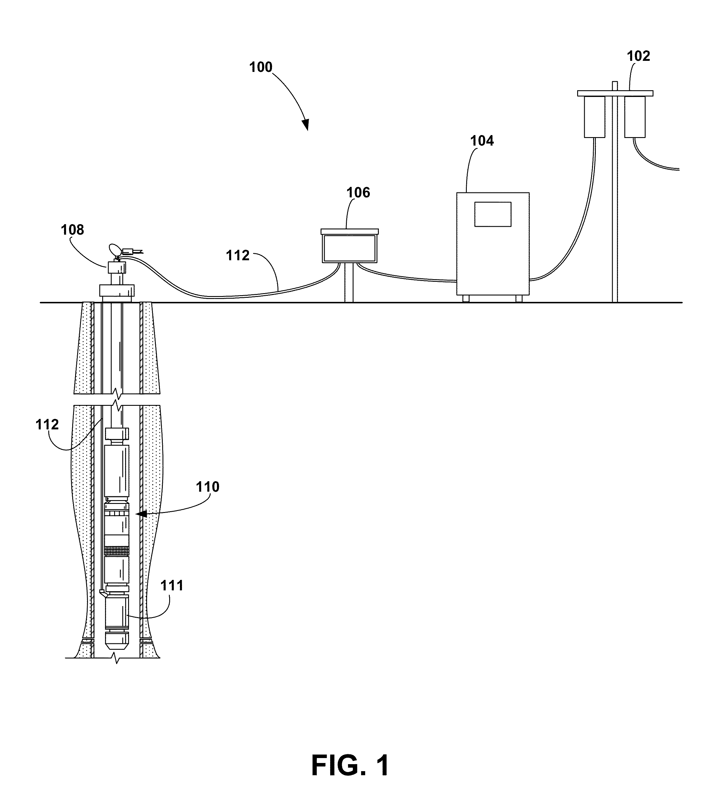
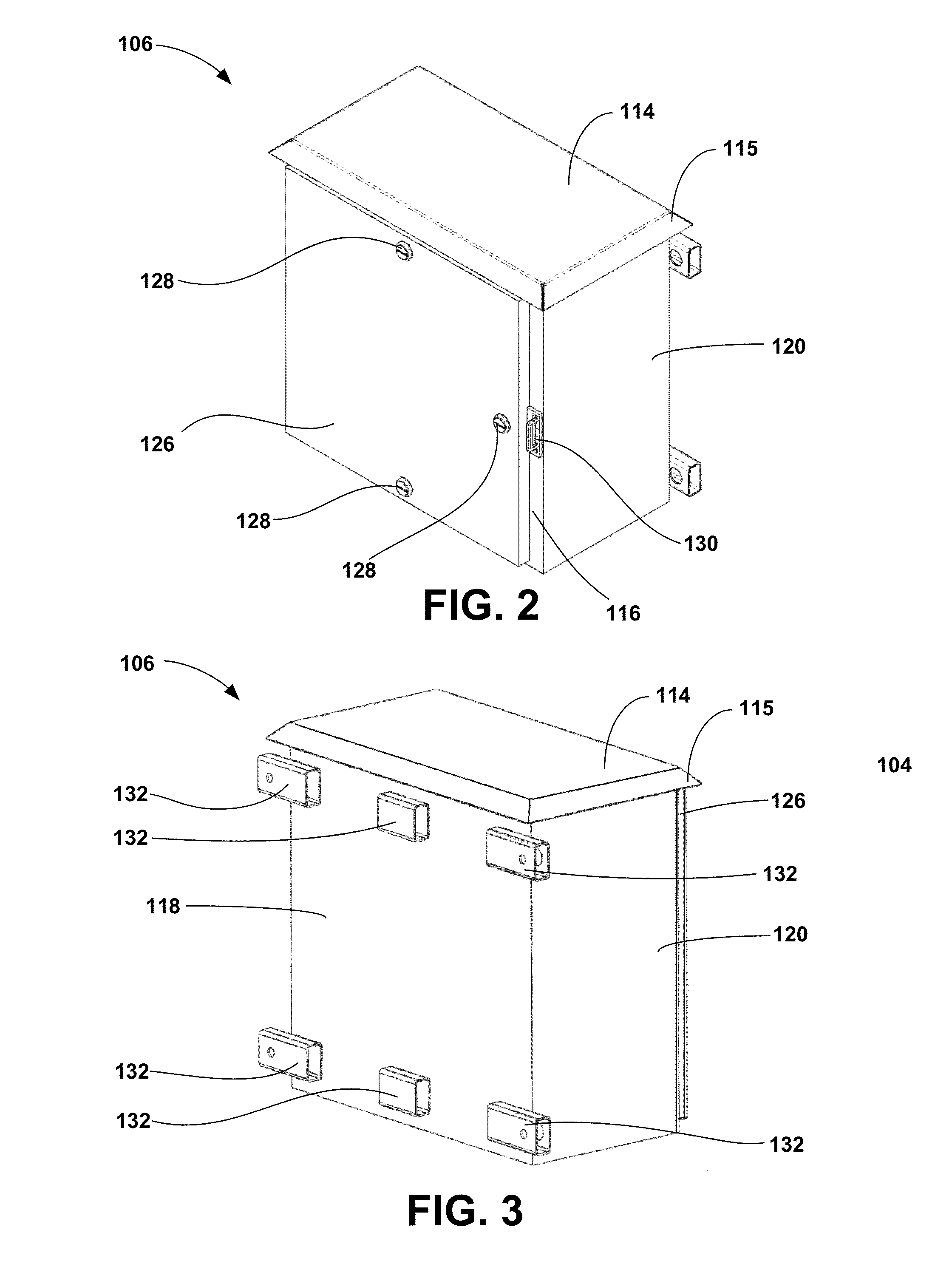
[0013]Now turning to FIGS. 2 and 3, shown therein are front and back isometric views, respectively, of a preferred embodiment of the vent box 106 of the present invention. The vent box 106 includes a top 114, a front 116, a back 118, at least two sides 120 and a bottom 122 (not shown in FIGS. 2 and 3...


PUM


Abstract

A vent box for venting gases present on a power cable used to provide power to an electric submersible pumping system includes a front, a back, a plurality of sides, a top and a bottom. The vent box includes one or more upper vents positioned along an upper edge of at least one of the front, the back or the plurality of sides. The vent box further includes one or more lower vents that extend through the bottom. The top includes a weather cap that extends downward from the top to partially conceal the one or more upper vents.

Description

FIELD OF THE INVENTION[0001]This invention relates generally to the field of surface equipment for downhole pumping systems, and more particularly, but not by way of limitation, to a vent box for venting downhole gases to the atmosphere.BACKGROUND[0002]Electric submersible pumping systems are often used to produce liquids and gases from subterranean wells. The electric submersible pumping system typically includes various surface-based equipment for providing power and control to the pumping system. The surface-based equipment may include transformers, switchboards, variable speed drives, junction boxes, and power cables. A transformer typically provides power through a power cable to the switchboard or variable speed drive and then is connected to a junction box. Power cables then travel from the junction box to the wellhead and down to the downhole motor and other downhole equipment.[0003]During operation of a downhole pumping system, gases from the well may travel up through the ...

Claims


Application Information

Patent Timeline
IPC IPC(8): H05K5/02
CPCH05K5/0217H05K5/0247H05K5/0204E21B43/128E21B43/121F04B49/065
Inventor VON TUNGELN, LANTZ
Owner GE OIL & GAS ESP
Why Eureka
Try Eureka