Tiltable Patient Ceiling Lift Assembly

a patient and assembly technology, applied in the field of patient ceiling lift assembly, can solve the problems of loss of assembly strength, loss of compactness of apparatus, loss of patient comfort, etc., and achieve the effect of only accommodating larger patients awkwardly, fixed motor units, and reducing the number of patients

Active Publication Date: 2017-12-14
ARJOHUNTLEIGH MAGOG
View PDF12 Cites 6 Cited by
  • Summary
  • Abstract
  • Description
  • Claims
  • Application Information

AI Technical Summary

Benefits of technology

[0010]The present disclosure relates to an improved patient ceiling lift system.

Problems solved by technology

Although the above-described solutions for very large patients can provide significant benefits, they can sometimes have the drawback of being suitable only to such patient morphology.
Otherwise, a room dedicated for very large sized patients can often be unoccupied for long periods of time.
While an arrangement which allows for the motor units to move apart can better accommodate a large patient, they can suffer from a loss of compactness of the apparatus and from loss of strength of the assembly.
Fixed motor units can, however, only accommodate larger patients awkwardly.

Method used


Image

  • Tiltable Patient Ceiling Lift Assembly
  • Tiltable Patient Ceiling Lift Assembly
  • Tiltable Patient Ceiling Lift Assembly

Examples


Embodiment Construction

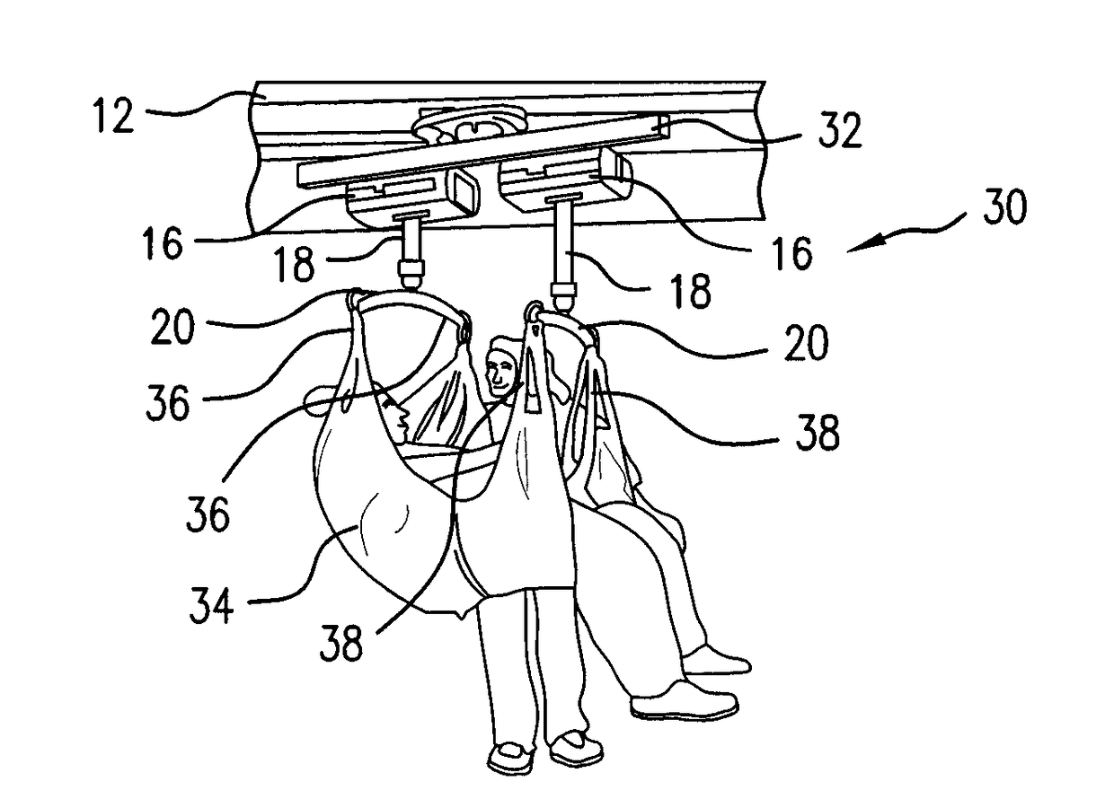
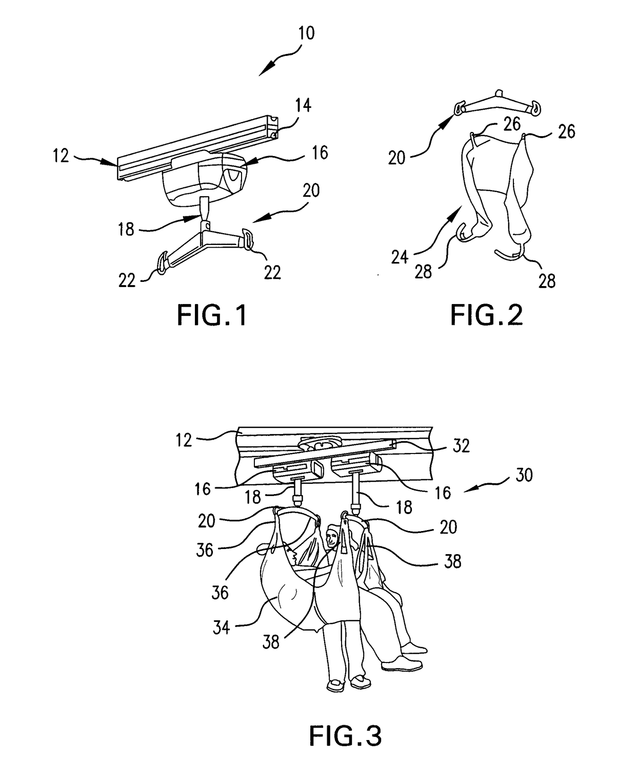
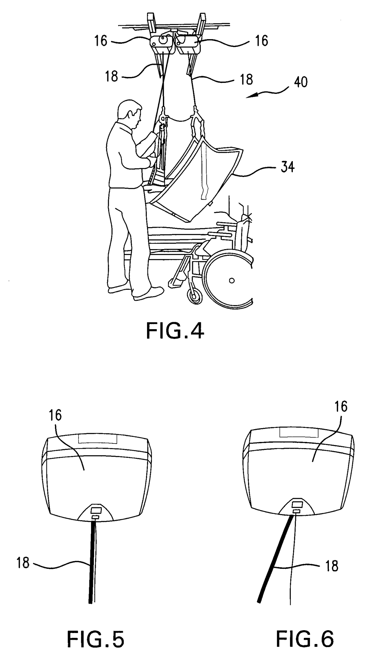
[0032]Referring first to FIG. 1, this shows a conventional ceiling lift system 10 which includes a rail 12 that is fixed to the ceiling structure of a patient care facility, such as a hospital, care home or the like. The rail 12 includes a downwardly depending channel 14. The system 10 may include a transmission, winding or coiling assembly, having for example a motor unit 16 which includes a wheel or roller (not shown) which runs within the downwardly depending channel 14 to allow the motor unit 16 to be moved in supported manner along the rail 12, as is known in the art.

[0033]The motor unit 16 is operatively associated with, coupled to and / or includes a tensile support member, such as a flexible element or strap 18, which in practice is attached to a motorised spool or drum within the motor unit 16, and which can be unwound from the spool to lengthen the strap 18 and wound on the spool to shorten the strap 18, again in known manner. One skilled in the art would appreciate that one...


PUM


Abstract

A patient ceiling lift system including motor units that are attached to independent pivotable support members of a support frame assembly. The motor units are able to pivot on the support frame and relative to one another, which enables the motor units to follow the loading direction on tension support members connectable to a patient sling and eliminate motor unit side loading.

Description

[0001]The present disclosure claims priority to U.S. provisional patent application No. 62 / 080,909, filed on Nov. 17, 2014, herein incorporated by reference in its entirety.TECHNICAL FIELD[0002]The present disclosure relates to a patient ceiling lift assembly for use, for example, in a hospital or care home.BACKGROUND OF THE DISCLOSURE[0003]Ceiling lifts for lifting and transporting patients have been in use for over twenty years. These types of patient lift are becoming more popular as they take up little space in a hospital or care home environment and are more efficient than floor lifts.[0004]A ceiling lift can be described as a motor unit able to move along one or more rails arranged as a rail system, fixed to the ceiling. A flexible member such as a strap extends from the motor unit and is attached to a spreader bar. A patient sling or harness is attached to the spreader bar. An electrically motorized mechanism in the motor unit allows the user to extend or shorten the strap so...

Claims


Application Information

Patent Timeline
Patent Type & Authority Applications(United States)
IPC IPC(8): A61G7/10
CPCA61G7/1042A61G7/1051A61G7/1034A61G7/1015A61G7/1076
Inventor BRULOTTE, DENIS-ALEXANDREFAUCHER, MARTINCUSTEAU-BOISCLAIR, OLIVIER
Owner ARJOHUNTLEIGH MAGOG
Why Eureka
Try Eureka