Static dissipating and conductive footwear

a technology of applied in the direction of fastenings, uppers, bootlegs, etc., can solve the problems that the footbeds and insoles of the conventional aftermarket orthotics cannot be used with static dissipation and conductive footwear, and the individual who requires custom orthotics are even more prone to problems, so as to achieve the effect of enhancing strength

Inactive Publication Date: 2017-12-21
WOLVERINE WORLD WIDE
View PDF2 Cites 0 Cited by
  • Summary
  • Abstract
  • Description
  • Claims
  • Application Information

AI Technical Summary

Benefits of technology

The present invention is a way to make footwear that can dissipate static electricity and make electrical contact with the wearer's foot. This can be done by adding conductive elements to the footwear, like to the insides of the tongue opening or the lacing system. These elements can be easily positioned and can be used with different types of footwear. The conductive elements can help improve the connection between the foot and the shoe, making them more comfortable and reliable. Additionally, the invention can be used with custom orthotics or aftermarket footbeds and shoe inserts.

Problems solved by technology

First, conventional aftermarket orthotics, footbeds and insoles cannot be used with static dissipating and conductive footwear because they are not conductive and would not provide a conductive path from the wearer's foot to the midsole.
This can significantly affect comfort for individuals that prefer aftermarket footbeds / insoles, and may present even greater problems for those individuals that require custom orthotics.
Second, it can be relatively costly to incorporate conductive elements into a footbed or insole in a way that reliably provides the desired electrical flow path.
Third, the presence of conductive elements in the footbed or insole can impact other performance characteristics, such as cushioning and support.
For example, design choices for the footbed or insole may be limited by the need to provide a conductive electrical flow path.

Method used


Image

  • Static dissipating and conductive footwear
  • Static dissipating and conductive footwear
  • Static dissipating and conductive footwear

Examples


Embodiment Construction

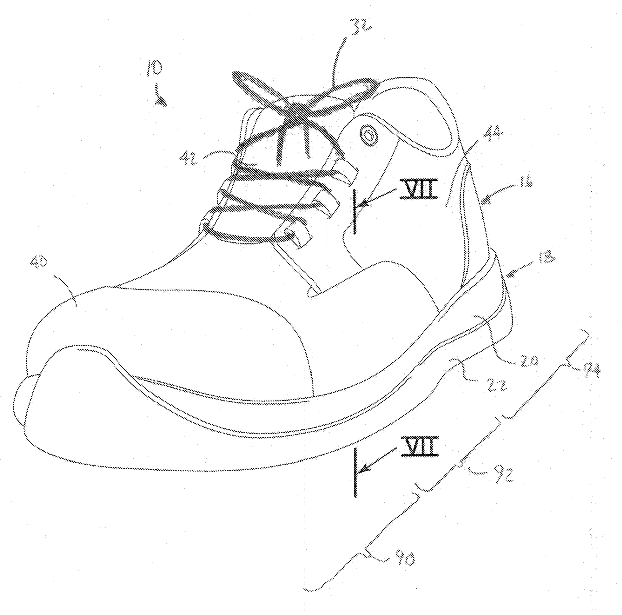
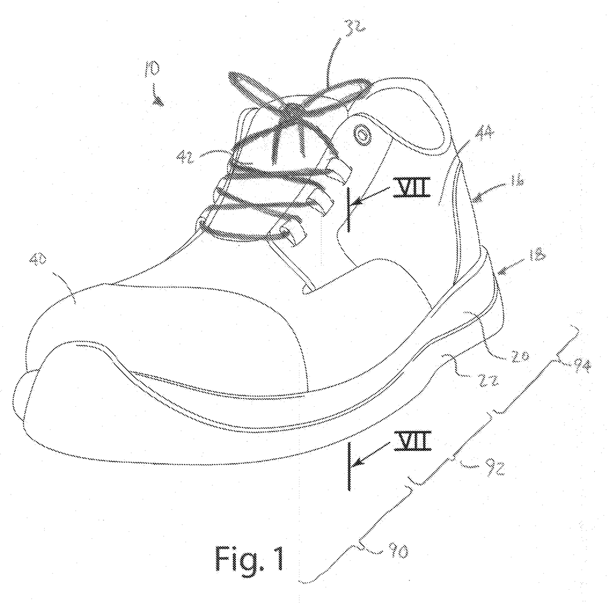
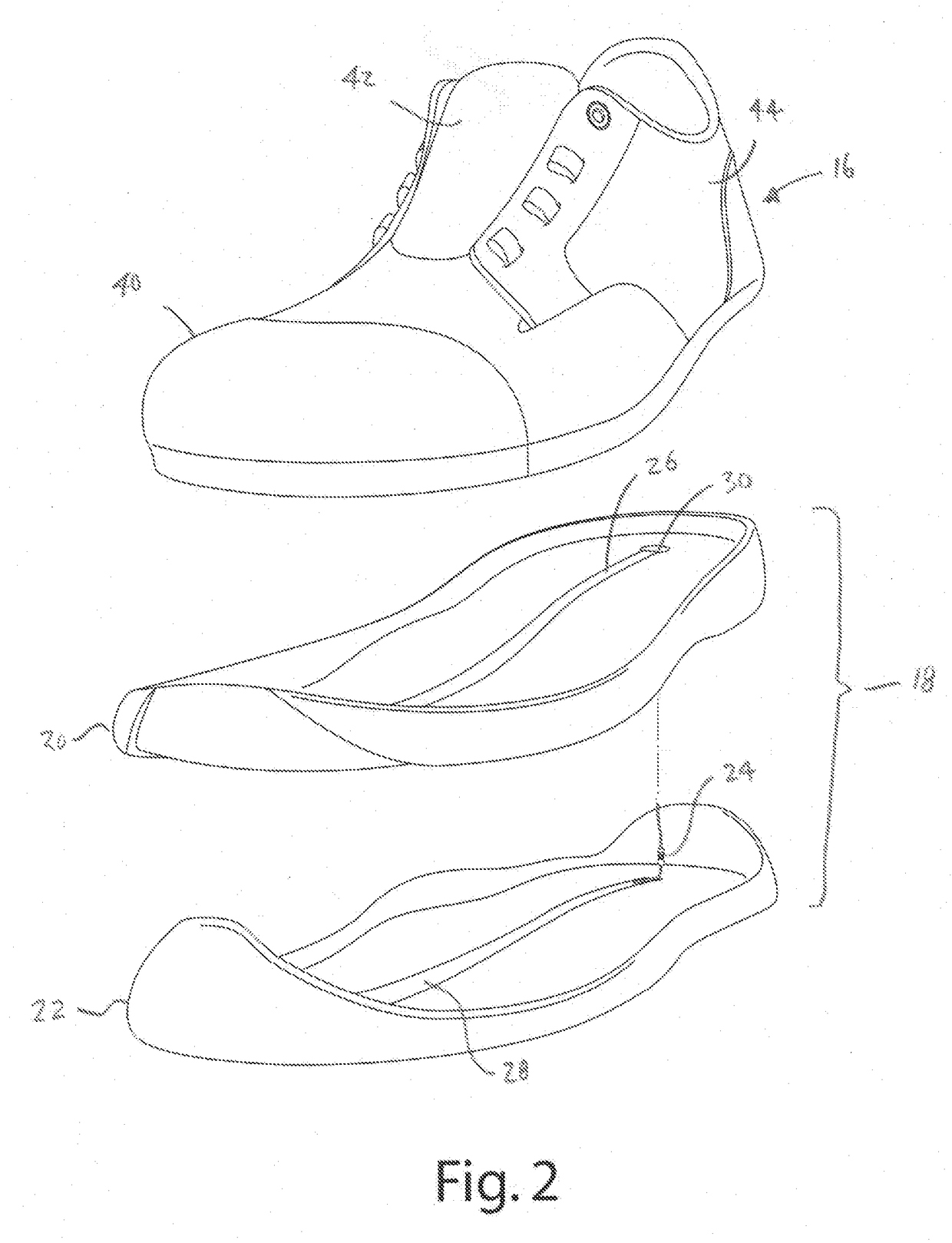
[0025]An article of footwear 10 incorporating a conductive system 12 in accordance with an embodiment of the present invention is shown in FIG. 1. The conductive system 12 includes an electrical flow path 14 in the upper 16 that may be configured to provide static dissipating footwear or conductive footwear. In the illustrated embodiment, the electrical flow path is provided by at least one conductive element 14 incorporated into the upper 16 and extending through a location where it will directly contact the wearer's foot. In some applications, the upper 16 may include a plurality of conductive elements 14 located in different regions to collectively provide improved electrical contact with the wearer's foot. The conductive element(s) 14 extend from the upper 16 to the sole assembly 18. For example, the conductive elements 14 may wrap beneath the upper 16 and extend along the top surface of the midsole 20 in engagement with one or more conductive elements incorporated into the mids...


PUM

PropertyMeasurementUnit
electrical resistanceaaaaaaaaaa
electrical flowaaaaaaaaaa
conductiveaaaaaaaaaa

Abstract

A static dissipating or conductive article of footwear with an electrical flow path in the upper. The upper includes at least one conductive element extending along at least a portion of the inside of the upper in a position where it will directly contact the wearer's foot. The upper may include a plurality of conductive elements located in different regions. The conductive elements may be positioned in line with a lacing system so that tightening of the laces urges the conductive elements toward the wearer's foot. The conductive elements may be a ribbon or other strip of fabric that includes one or more conductive threads. The ribbon or fabric strip may be woven in and out of a lining material on the inside of the upper.

Description

BACKGROUND OF THE INVENTION[0001]The present invention relates to static dissipating and conductive footwear, and methods for manufacturing such footwear.[0002]Static dissipating and conductive footwear are available from a variety of footwear suppliers. Conventional static dissipating and conductive footwear are designed to provide a conductive path from wearer's foot through an article of footwear to ground. In use, this flow path allows static electricity and other electrical charges to dissipate from an individual to the ground. In the context of static dissipating footwear, an appropriately-sized resistor is generally provided along the flow path. For example, applicable ASTM standards provide for static dissipative footwear to have electrical resistance between 1M ohm and 100M ohm. Conductive footwear is designed to have significantly lower electrical resistance. Applicable ASTM standards provide for conductive footwear to have electrical resistance between 0 and 500K ohms.[00...

Claims


Application Information

Patent Timeline
Patent Type & AuthorityApplications(United States)
IPC IPC(8): A43B7/36A43B23/26A43B23/02A43B3/00A43B13/18A43B13/12A43C1/00A43B23/07
CPCA43B7/36A43C1/00A43B23/26A43B23/07A43B3/0005A43B13/187A43B13/181A43B13/12A43B23/0225
InventorGOULD, MATTHEW L.
OwnerWOLVERINE WORLD WIDE