Instrument for inserting a spinal implant and a spinal implant

a technology for applied in the field of spinal implants and operating instruments, can solve the problems of increasing the risk of nerve structures that must be passed through, cumbersome need for several tools, and affecting the safety of patients, and achieve the effect of causing as little trauma

Active Publication Date: 2018-01-25
MEDICON EG CHIRURGIEMECHANIKER GENOSSENSCHAFT
View PDF3 Cites 30 Cited by
  • Summary
  • Abstract
  • Description
  • Claims
  • Application Information

AI Technical Summary

Benefits of technology

[0014]The object of the present invention consists in providing an operating tool and a spinal im

Problems solved by technology

However, because most of these pathologies also require surgical procedures to the structures which are dorsal of the spinal canal, the question arises as to whether the additional anterior procedure cannot be avoided, and the reconstructive measures of the anterior column can be carried out from dorsal, past the thecal sac and the nerve roots.
The need for several tools is cumbersome and increases the risk for the nerve structures that must be passed through during each change.
In addition, control of the current implant position is temporarily lost in the depth of a (bleeding) wound, and, in some instances, the

Method used


Image

  • Instrument for inserting a spinal implant and a spinal implant
  • Instrument for inserting a spinal implant and a spinal implant
  • Instrument for inserting a spinal implant and a spinal implant

Examples


Embodiment Construction

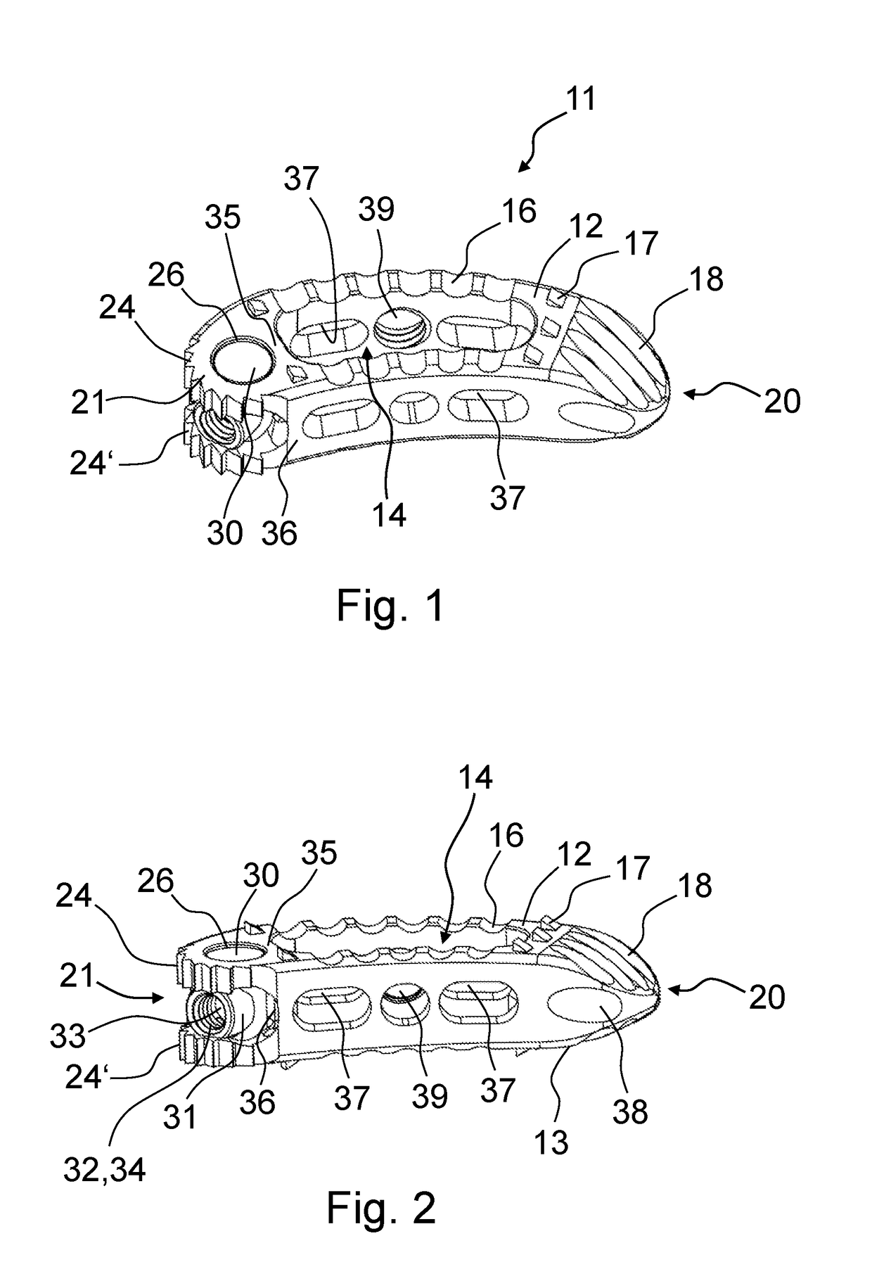
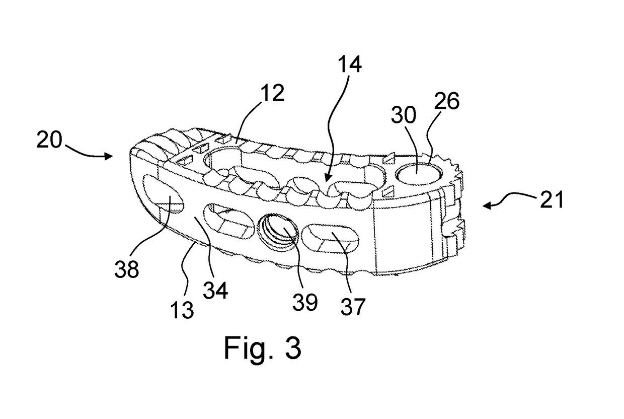
[0045]The implant 11 in FIGS. 1, 2 and 3 has an elongated, slightly curved banana-shaped form with an upper side 12 and a lower side 13. A vertically extending passage opening 14 extends through the upper 12 and lower side 13 of the implant 11, said passage opening 14 extending in the central region of the implant 11 and serving to receive bone material and for better ossification. Due to their cage-like appearance, such implants 11 are also referred to as “cages”.

[0046]Furthermore, there are grooves 16 and mandrels 17 on the upper 12 and lower side 13 of the implant 11, which serve to improve the fixing of the implant 11. The grooves are arranged obliquely in order to bring the implant 11 into a radius and finally into the 90° position when it is inserted.

[0047]The two lateral ends 20, 21 of the implant 11 are different. The implant 11 is chamfered on one lateral end 20, the front end, and the upper 12 and lower side 13 extend towards one another. This end 20 is formed to be wedge-...


PUM


Abstract

The invention relates to an operating instrument for minimally invasive or conventional implanting of a spinal implant into the intervertebral space comprising an outer tube which has a hollow handle on its proximal end, wherein the inner rod can be moved in the outer tube and the hollow handle, and the inner rod is provided with a threaded region which extends beyond the distal end of the outer tube, wherein the threaded region serves for fastening to the rear region of an implant and for tensioning the implant with its rear region against the distal end region of the outer tube, wherein the distal end region of the outer tube is at least partially adapted to the rear region of the implant, wherein the tensioning of the implant against the outer tube takes place by means of a tensioning device having a lever.

Description

CROSS-REFERENCE TO RELATED APPLICATIONS[0001]This application claims priority to German patent application 10 2016 113 488.0, titled: Instrument for inserting a spinal implant and a spinal implant, Filed 21 Jul. 2016.STATEMENT REGARDING FEDERALLY SPONSORED RESEARCH OR DEVELOPMENT[0002]Not Applicable.BACKGROUND OF THE INVENTIONTechnical Field[0003]The present invention relates to operating instruments and spinal implants adapted thereto which can be inserted into the intervertebral space from all usual, conventional, and less or minimally invasive access variants and, for example in the case of TLIF or PLIF, can be brought into the optimal permanent position locally in a mechanically safe manner.Related Background Art[0004]In the event of advanced degeneration of intervertebral discs in the lumbar spine region, stiffening surgery is often the best option for treatment. For this, the remains of the worn intervertebral discs are removed, and bone or bone replacement material is inserte...

Claims


Application Information

Patent Timeline
IPC IPC(8): A61F2/46
CPCA61F2/4611A61F2002/30538A61F2002/30133A61F2002/4625A61F2/4465A61F2/4455A61F2/447A61F2002/30471A61F2002/30523A61F2002/4627A61F2002/4628A61F2002/4629A61F2/4603
Inventor BOEHM, HEINRICHBURGER, ANDREASWIDMAIER, GERDWENZLER, KLAUS
Owner MEDICON EG CHIRURGIEMECHANIKER GENOSSENSCHAFT
Why Eureka
Try Eureka