Tattooing and permanent make-up device

a makeup device and tattoo technology, applied in the field of tattooing and permanent makeup devices, can solve the problems of permanent injury to the person undergoing treatment, and achieve the effects of avoiding any injury to the operator and the client, avoiding permanent injury, and optimum vibration absorption

Inactive Publication Date: 2022-04-14
BIOTEK
View PDF1 Cites 0 Cited by
  • Summary
  • Abstract
  • Description
  • Claims
  • Application Information

AI Technical Summary

Benefits of technology

[0012]According to another characteristic feature of the invention, the electric conducting means on the attachment part of the needle-holder cartridge are formed by an annular or semi-annular plate of electrically conductive material arranged on the end of the attachment part of the needle-holder cartridge. Once the needle-holder cartridge is operatively mounted on the grip portion of the device, the plate of electrically conductive material establishes an electrical contact between the terminals of the circuit for energizing the electric motor of the device, allowing energizing of said electric motor when the operator presses the button for switching on the device. It should be pointed out that the electric conducting means may establish the electrical continuity of the electric circuit energizing the electric motor of the device only if the needle-holder cartridge has been operatively mounted on the grip portion of the device. For example, if a screw connection is used, the electrical continuity is established only if the needle-holder cartridge is screwed fully onto the grip portion of the device. Only in this situation is it possible to provide an electric contact and close the circuit which allows the current flow from the power supply to the electric motor, thereby determining whether the device itself is working or not. This measure is intended to ensure a greater degree of safety, preventing the device from being able to be operated in unsuitable circumstances or accidentally, avoiding any injury to the operator and the client.
[0013]According to a further characteristic feature of the invention, the attachment part of the needle-holder cartridge which serves for connection to the grip portion is made of a plastic material with optimum vibration-absorbing properties, so as to be able to dampen the vibrations generated by the drive unit. Advantageously, the total or partial absorption of the vibrations generated by the drive unit of the device results in a greater precision with regard to incision in the skin and a greater degree of safety in particular during the permanent make-up treatment of the eye-lashes or the area around the eyes. As is known, the treatment of these parts of the patient requires a greater precision and stability of the needle-holder cartridge since an undesirable vibration may result in the needle coming into contact with the cornea of the eye, causing serious and even permanent injury to the person undergoing treatment. The reduction of the vibrations is also advantageous, in clinical and operational terms, for the operator's hand, the operator often working for many hours during the day and the vibrations transmitted by the device may result in aching and even disorders due to the continuous vibrations affecting the operators hand. Purely by way of example, the plastic materials which can be used for the attachment part of the needle-holder cartridge may be elastic rubber or ABS with a silicone rubber additive. The needle-holder cartridge body is preferably made of a plastic material more rigid than that of the attachment part. For example, ABS may be used as plastic material for the body of the needle-holder cartridge. The body of the needle-holder cartridge and its attachment part may be produced individually and assembled together or may be co-moulded, namely moulded as a single piece made of two different plastic materials.
[0014]According to another characteristic feature of the invention, the needle-holder cartridge has a pointed cone-shaped end part intended to come into contact with the skin of the person undergoing skin treatment. This part forms a reservoir containing the liquid pigment used in the treatment, as well as a guide for the end part of the needle. The needle is supported and guided by a calibrated cylindrical nozzle which is located at the end of the end part of the needle-holder cartridge which is intended to reduce or eliminate the sideways movements of the needle inside the said tip, increasing the working precision and reducing the risk of tattooing lines being formed outside of the desired zones. At the same time, owing to its particular internal form, the calibrated cylindrical nozzle at the end of the end part ensures a suitable flow of the liquid pigment towards the needle tip and therefore towards the skin of the person undergoing treatment, reducing in fact the technical execution time and the trauma affecting the skin part treated. It should be pointed out that the shorter the insertion time of the needle tip in the skin, the smaller will be the trauma for the person being treated, with a consequent rapid recovery and a reduction in the possibility of contracting infections during bleeding of the treated skin part. The particular internal form of the calibrated cylindrical nozzle at the end of the end part of the needle-holder cartridge is such that there are parts protruding from the inner walls of the guide nozzle which, being in contact with the needle shaft during its movement, ensure the absolute stability thereof, preventing any lateral oscillation thereof, alternating with hollow parts which by means of capillarity allow the liquid pigment to flow towards the tip of the said needle. This particular form of the cylindrical guide nozzle is suitable for every type of needle used in practice and reconciles in an innovative manner the two requirements of lateral stability and passage of the liquid pigment.
[0015]According to another characteristic feature of the invention, the device is provided with a conical rubber / silicone membrane inside the needle-holder cartridge which prevents the backflow of liquid pigment and organic pigments towards the body of the device. The membrane is however positioned so as to perform a new function, namely retain the needle inside the needle-holder cartridge when the latter is not operatively mounted on the device body, so as to prevent the tip of needle from coming out and accidentally pricking the operator. The invention, while adopting a conical membrane similar to those used in the known devices of the conventional type, proposes positioning it in an inverted manner with respect to the conventional positioning on the stem of the needle-holder head, so that owing to the elastic properties of the rubber / silicone polymers, it is also able to perform the function of preventing the needle from coming out of the tip of the needle-holder cartridge when the latter is not operatively mounted on the device. By mounting the conical membrane in an overturned manner it is possible to obtain an elastic effect which prevents the needle from coming out, while allowing the membrane to perform the usual function of retaining the liquid pigment in the event of a backflow towards the device or parts thereof.

Problems solved by technology

As is known, the treatment of these parts of the patient requires a greater precision and stability of the needle-holder cartridge since an undesirable vibration may result in the needle coming into contact with the cornea of the eye, causing serious and even permanent injury to the person undergoing treatment.

Method used


Image

  • Tattooing and permanent make-up device
  • Tattooing and permanent make-up device
  • Tattooing and permanent make-up device

Examples


Embodiment Construction

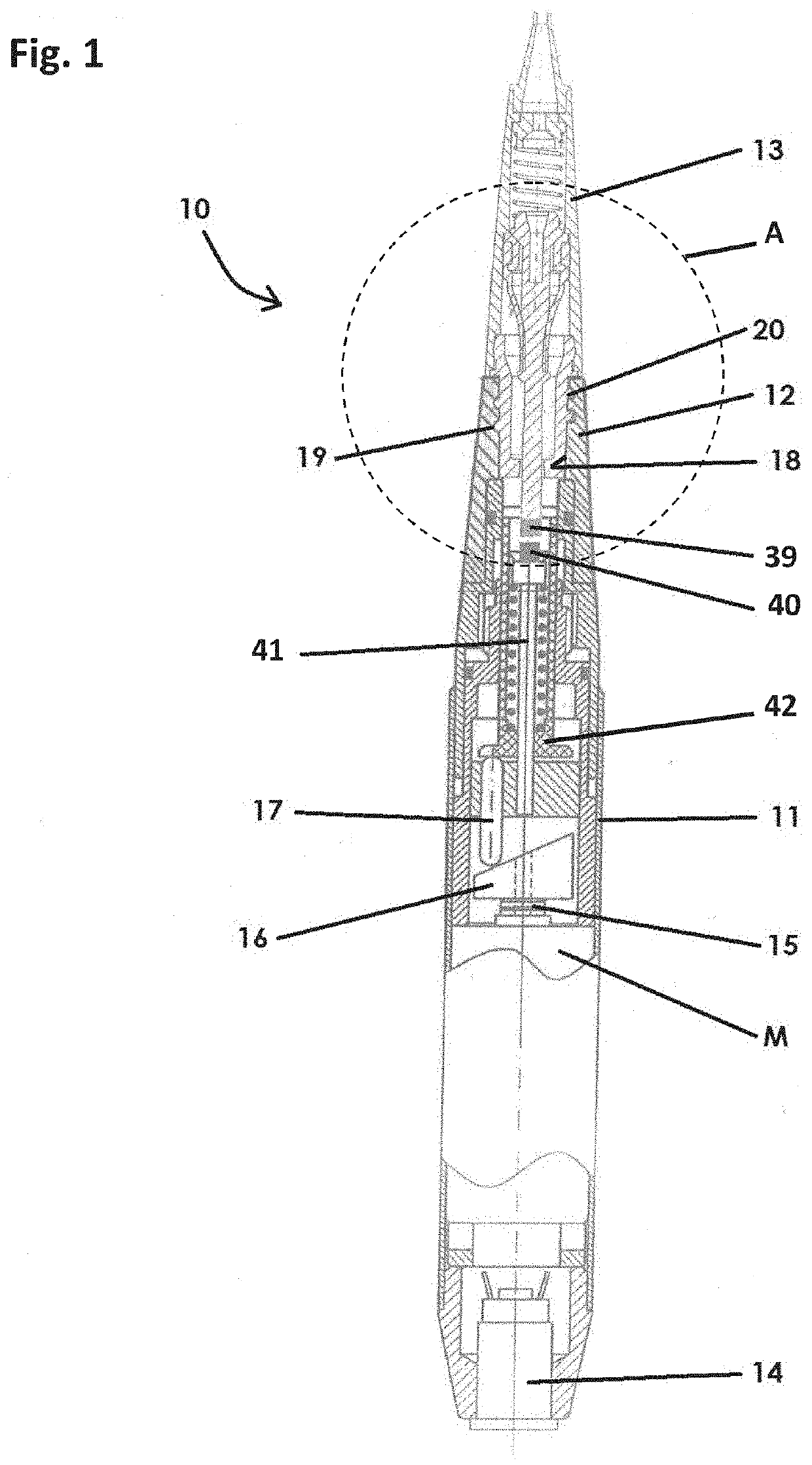
[0024]FIG. 1 shows a tattooing or permanent make-up (PMU) device according to the present invention, denoted overall by 10. The device 10 comprises, in a manner known per, a body 11, substantially in the form of a writing tool, having a front end part 12, configured to allow fixing of a disposable needle-holder cartridge 13, and a rear connector 14, suitable for connection to a low-voltage electric power source (not shown).

[0025]The body 11 of the device houses internally an electric drive motor M, whose drive shaft 15 is connected to a cam 16 of a cam transmission mechanism for transforming the rotary motion of the drive shaft 15 into a reciprocating rectilinear movement of a tappet assembly 17, as typically occurs in tattooing and PMU devices of this kind known in the art.

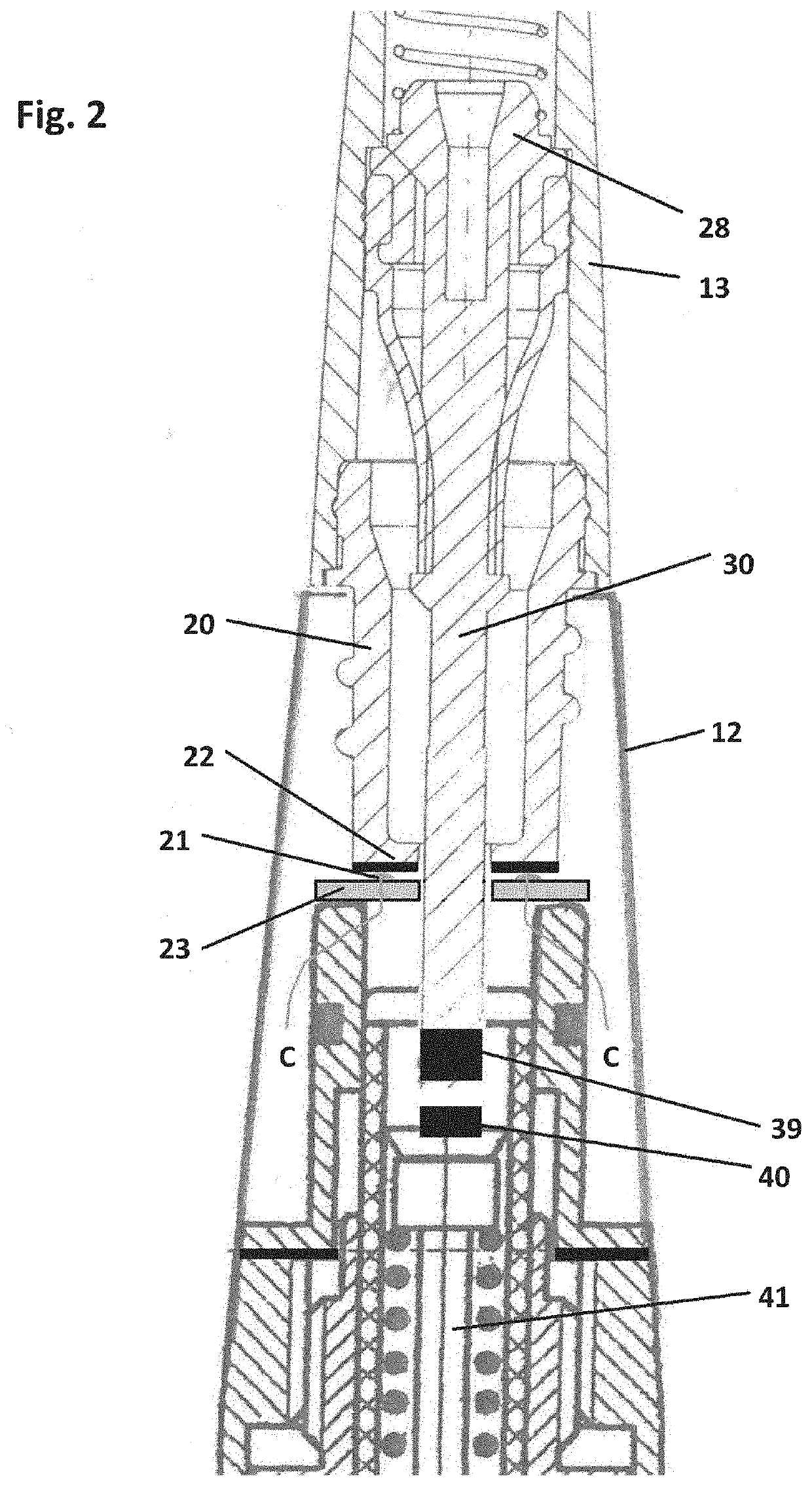
[0026]The front end part 12 of the body 11 has a suitable housing 18 with a threaded part 19 designed to receive a corresponding threaded attachment part 20 of the disposable needle-holder cartridge 13. Obviously...


PUM


Abstract

The present invention relates a device (10) for applying a tattoo or a permanent make-up or a similar skin treatment. The device has a grip portion (11) containing a drive unit, and a disposable needle-holder cartridge (13) which can be coupled to the grip portion (11). The needle-holder cartridge (13) comprises an attachment part (20) for attachment to the grip portion (11), a needle-holder head (28) with a stem (30) which partially protrudes from the attachment part (20), a needle supported by the needle-holder head (28), a tip (25) having a needle-guide nozzle (27). The needle-holder head (28) is arranged in the needle-holder cartridge (13) for a linear movement along the axial direction of the needle-holder cartridge (13), in order to cause the oscillation of the end of the needle in and out of the tip (25) of the needle-holder cartridge (13). The drive unit comprises an electric motor (M) having a drive shaft (15), an actuator shaft (41) which can be coupled to the stem (30) of the needle-holder head (28), a cam mechanism (16,17) operatively connected to the drive shaft (15), for transforming the rotary motion of the drive shaft (15) into a linear motion of the actuator shaft (41). For coupling of the actuator shaft (41) with the stem (30) of the needle-holder head (28) magnetic coupling means (39, 40) are provided at the end of the actuator shaft (41) and, respectively, at the end of the part of the stem (30) of the needle-holder head (28) which protrudes from the attachment part (20) of the needle-holder cartridge (13). The magnetic coupling means (30, 40) are adapted to stably, but releasably connect the actuator shaft (41) to the part of the stem (30) protruding from the attachment part (20) of the needle-holder cartridge (13), when the needle-holder cartridge (13) is operatively mounted on the grip portion (11). The attachment part (20) of the needle-holder cartridge (13) is provided with electric conducting means (22) adapted to come into contact with the electric terminals (21) of the electric circuit for energizing the electric motor (M) of the device only when the needle-holder cartridge (13) is operatively mounted on the grip portion (11) of the device, in order to establish electric continuity between the electric terminals (21) of the electric circuit for energizing the electric motor (M) of the device.

Description

RELATED APPLICATIONS[0001]This application claims priority to Italian Application No. 102020000024154, filed Oct. 14, 2020, the contents of which are incorporated by reference herein.DESCRIPTIONField of the invention[0002]The present invention relates to a device for performing artistic tattooing, aesthetic tattooing, permanent make-up, tricopigmentation and in general pigmentation of any area of the human body.Prior Art[0003]As is known, artistic tattooing, aesthetic tattooing, permanent make-up (PMU), tricopigmentation, dermopigmentation and microneedling are all treatments which have the purpose of implanting a pigment with different effects in the human skin. Currently, in order to perform these treatments, conventionally devices provided with a single-use, i.e. disposable, needle-holder cartridge and operated by an electric motor are used.[0004]A lot has been done in order to make these devices safer, more hygienic and easier to use. However, despite the constant improvement of...

Claims


Application Information

Patent Timeline
Patent Type & Authority Applications(United States)
IPC IPC(8): A61M37/00
CPCA61M37/0084
Inventor FROIO, MASSIMO
Owner BIOTEK
Why Eureka
Try Eureka