Scroll compressor

Active Publication Date: 2018-06-14
HANON SYST
View PDF0 Cites 0 Cited by
  • Summary
  • Abstract
  • Description
  • Claims
  • Application Information

AI Technical Summary

Benefits of technology

[0032]According to the exemplary embodiments of the present invention, it is possible to stably revolve the orbiting scroll by coping with the tolerances occurring during the relative movement of the orbiting scroll of the scroll compressor with respect to the fixed scroll.
[0033]According to the exemplary embodiments of the present invention, the structure of the ring member may be changed so that the ring member stably and relatively moves in the seating groove to reduce the friction force depending on the relative rotation of the ring member and minimize the st

Problems solved by technology

Further, the scroll compressor is rarely subjected to a change in torque required for the compression and continuously performs the intake and the compression, and as a result, may have reduced noise and vibration.
One of the important factors in the scroll compressor is leakage and lubrication problems between the fixed scroll and the orbiting scroll.
On the other hand, a resistance due to friction needs to be minimized to smoothly orbit the orbiting scroll with respect to the fixed scroll, but the leakage and lubrication problems have a conflict relationship with each other.
That is, when the end of the wrap strongly adheres to the surface of the mirror plate portion, the leakage is reduced, but the friction is

Method used


Image

  • Scroll compressor
  • Scroll compressor
  • Scroll compressor

Examples


Example

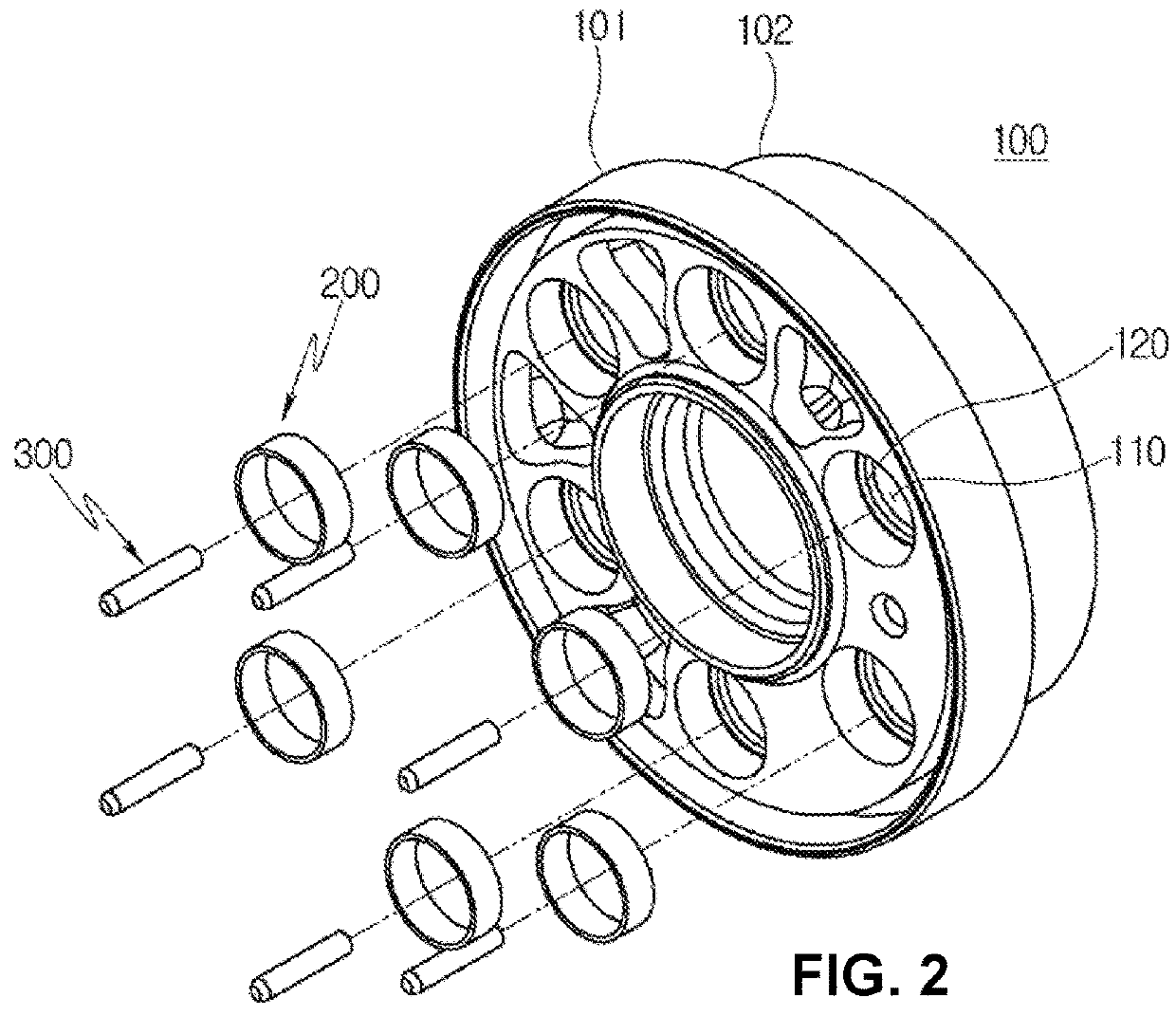
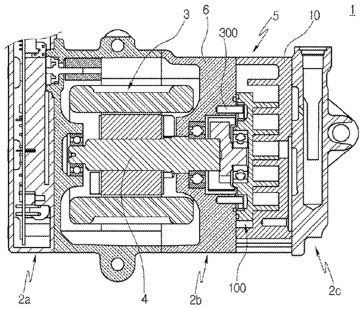
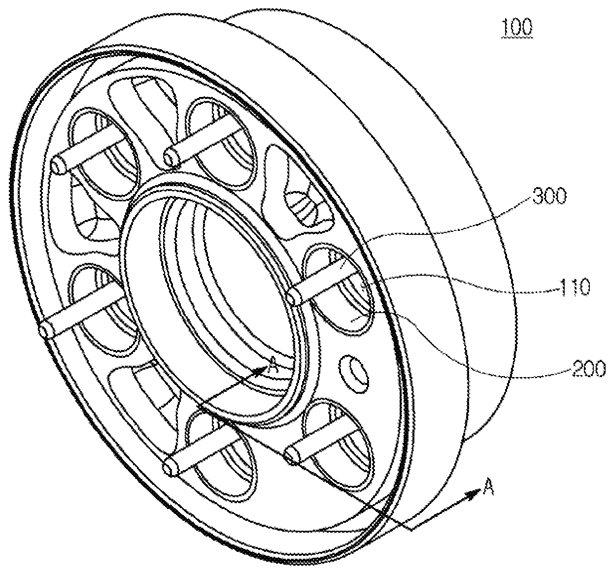
[0048]A scroll compressor according to a first exemplary embodiment of the present invention will be described with the accompanying drawings. For reference, FIG. 1 is a longitudinal cross-sectional view of a scroll compressor according to a first exemplary embodiment of the present invention, FIG. 2 is an exploded perspective view of an orbiting scroll according to a first exemplary embodiment of the present invention, FIG. 3 is a coupled perspective view of FIG. 2, and FIG. 4 is a partial cross-sectional view taken along the line A-A of FIG. 3.

[0049]Referring to FIGS. 1 to 4, a scroll compressor 1 according to a first exemplary embodiment of the present invention may be configured to include a front housing 2a forming an appearance and formed at a position of an inlet into which a refrigerant is sucked, an intermediate housing 2b, and a rear housing 2c, in which the intermediate housing 2b has a driver 3 and a compression unit 5 embedded therein and the driver 3 includes a stator,...


PUM


Abstract

The present invention relates a scroll compressor. According to an exemplary embodiment of the present invention, the scroll compressor includes: an orbiting scroll configured to be seated on one surface of a main frame and provided with a plurality of seating grooves along a circumferential direction; a stepped part configured to be formed in the seating groove; a ring member configured to be inserted into the seating groove and have a lower surface adhering to the stepped part; and a guide pin configured to have one end fixed to the main frame and the other end extended in an inside length of the ring member, in which the guide pin has the end maintained in a spaced state from the stepped part.

Description

CROSS-REFERENCES TO RELATED APPLICATIONS[0001]This patent application is a United States national phase patent application based on PCT / KR2015 / 006249 filed on Jun. 19, 2015, which claims the benefit of Korean Patent Application No. 10-2015-0031824 filed on Mar. 6, 2015. The disclosures of the above patent applications are hereby incorporated herein by reference in their entirety.BACKGROUND OF THE INVENTIONField of the Invention[0002]Exemplary embodiments of the present invention provide a stable revolution depending on an operation of an orbiting scroll, and more particularly, to a scroll compressor capable of minimizing deformation and noise occurrence due to a stress concentration on a guide pin which occurs during a revolution and vertical movement based on a rotating shaft depending on an operation of an orbiting scroll.Description of the Related Art[0003]Generally, a scroll compressor is a compressor using a fixed scroll having a spiral wrap and an orbiting scroll orbiting with...

Claims


Application Information

Patent Timeline
IPC IPC(8): F04C18/02F04C29/00
CPCF04C18/0215F04C29/0057F04C29/0078F04C2240/30F04C29/00F01C17/06
Inventor LIM, JAE HOONLIM, KWEON SOOJEONG, SOO CHEOLKIM, HONG MIN
Owner HANON SYST
Why Eureka
Try Eureka