Stabilized platform for camera

Inactive Publication Date: 2017-09-05
MY RES
View PDF10 Cites 0 Cited by
  • Summary
  • Abstract
  • Description
  • Claims
  • Application Information

AI Technical Summary

Benefits of technology

[0014]Purpose of the invention is to reduce friction forces of rotational parts between an

Problems solved by technology

Large frames have disadvantages such as reduced structural rigidity, incr

Method used


Image

  • Stabilized platform for camera
  • Stabilized platform for camera
  • Stabilized platform for camera

Examples


Embodiment Construction

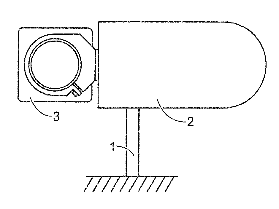
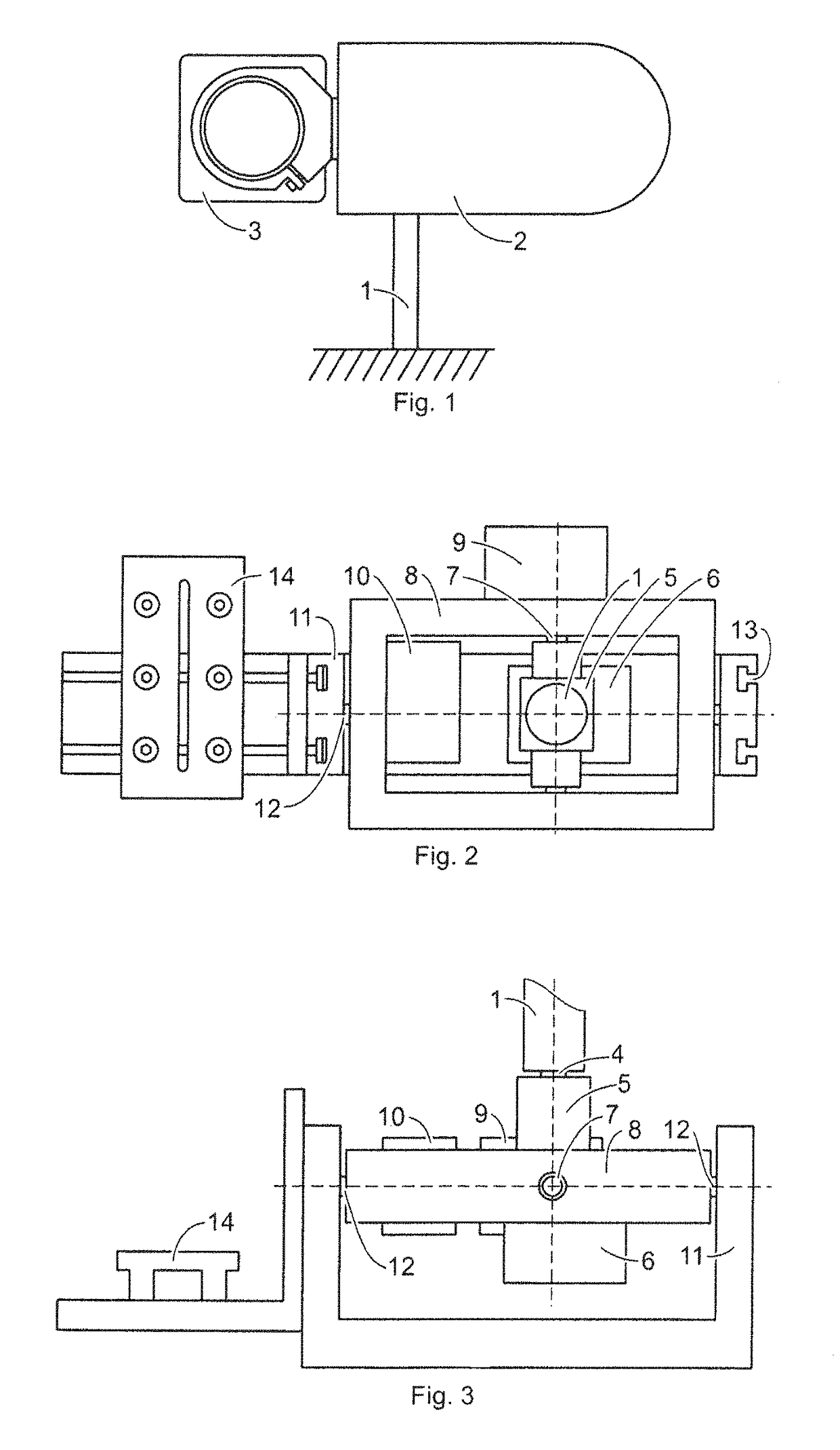
[0020]With reference to FIGS. 1-3, the stabilized platform includes a leg (1), a housing (2), and an adjustable platform (14) supporting and stabilizing a video camera (3). With reference to FIGS. 2-3, the stabilized platform provides a gimbal with three controlled axes of rotation.

[0021]The stabilized platform further includes an axial unit with:

[0022]i) a first connector (4) located on a first axis of rotation (4) called a panoramic rotation axis (4) which extends along a length of the leg (1),

[0023]ii) two second connectors (7) located on a second axis of rotation (7) called a transverse tilting axis (7), and iii) two third connectors (12) located on a third axis of rotation (12) called a longitudinal inclination axis.

[0024]The first, second, and third axes of rotation intersect at a common intersection point. The second axis of rotation (7) and the third axis of rotation (12) are perpendicular one to another

[0025]As shown in FIGS. 2-3, the axial unit further includes a horizonta...


PUM


Abstract

The invention is related to controlled mechanical platforms for video cameras. A device rotating on a support allows control and stabilization of the position of a camera being rotatable in three dimensions. The construction described above can improve stability of the platform. Vibration level transmitted from the unstable base to the platform is reduced. Areas of application: portable stabilizers for operators, installation of cameras on vehicles, cranes and cables, unmanned machines.

Description

BACKGROUND OF THE INVENTION[0001]Field of the Invention[0002]The invention is a stabilized platform for one or more cameras.[0003]This invention relates to platforms for video cameras for rotation in multiple directions at a common intersection point of three rotational axes.[0004]With the invention, a position and stability of the mounted video camera(s) can be controlled using a platform having center of mass of a stabilizing part coinciding with rotational axes.[0005]Description of the Related Art[0006]U.S. patent application Ser. No. 12 / 669,480 and Chinese patent application No. 20111380351.6 describes mechanisms in which a video camera is located in the center of the rotating unit.[0007]Locking elements for axes elements and servo drives are mounted on the sides.[0008]The axes elements are fixed to the frames encircling the camera, making said frames quite large.[0009]Large frames have disadvantages such as reduced structural rigidity, increased errors in the production and ope...

Claims


Application Information

Patent Timeline
IPC IPC(8): F16M11/12F16M11/18F16M11/10G03B17/56F16M11/20
CPCF16M11/123F16M11/10F16M11/18F16M11/2071G03B17/561F16M2200/04
Inventor ZAICEVSKIJ, ALEKSEJ
Owner MY RES
Why Eureka
Try Eureka