Manual cutting machine

Active Publication Date: 2021-10-19
ROMWAY ZJ MASCH MFG CO LTD
View PDF8 Cites 0 Cited by
  • Summary
  • Abstract
  • Description
  • Claims
  • Application Information

AI Technical Summary

Benefits of technology

[0018]1. The tail of the push rod is angled relative to the push rod and is provided with the handball, and the operator can hold the handball to rotate the push rod by moving the hand joints without drastically swinging the shoulder joints, so that the comfort in use is improved.
[0019]2. The switch is used to control the flow of lubricating oil in the oil can arranged at the top of the slider, the lubricating oil can flow onto the wool felt via the oil passage in the slider, and then the sliding rods are lubricated by the wool felt, so that the frictional force between the slider and the sliding rods is reduced, and the connecting block can move on the sliding rods more smoothly.
[0020]3. The slider is disposed around the left cylindrical sliding rod and the right cylindrical sliding rod through the left bearing and th

Problems solved by technology

However, such cutting machines are inconvenient to operate and are dangerous to a certain extent due to the high-speed rotation of the grinding wheel.
This manual tile cutting machine has the defect that both the hand joints and

Method used


Image

  • Manual cutting machine
  • Manual cutting machine
  • Manual cutting machine

Examples


Example

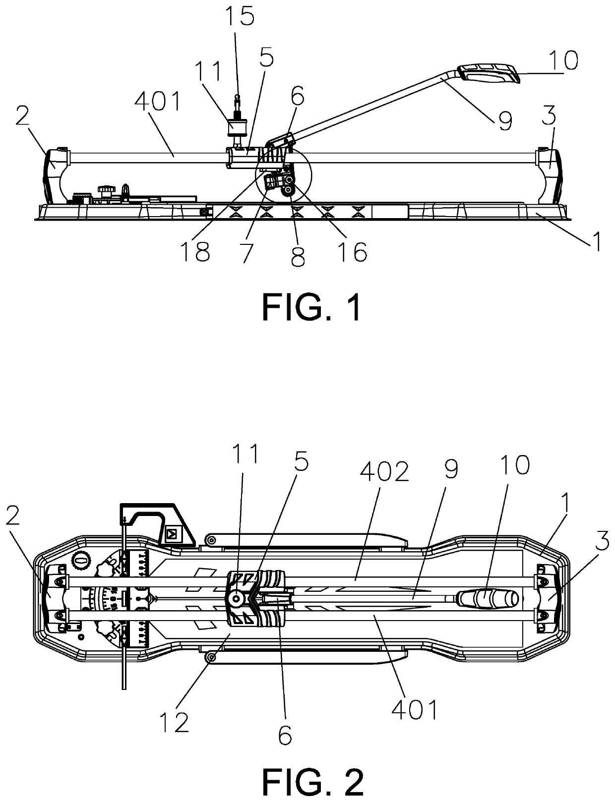
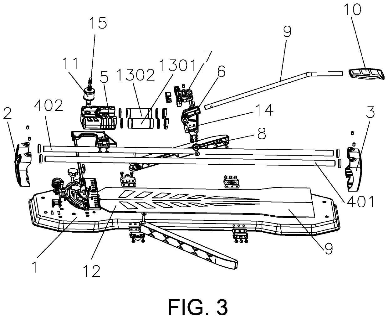
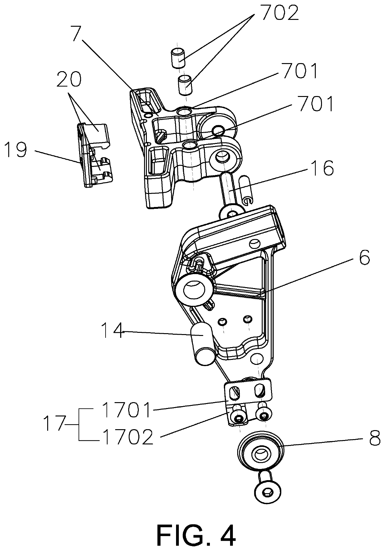
[0029]As shown in FIGS. 1-4, a manual cutting machine comprises a base plate 1. A rubber cushion 12 is arranged on the upper surface of the base plate 1, and a board is placed on the rubber cushion 12 to be prevented from moving in the cutting process, so that irregular cut faces of the board are avoided. A front support 2 and a rear support 3 are fixedly arranged at two ends of the base plate 1. A left cylindrical sliding rod 401 and a right cylindrical sliding rod 402 are mounted between the front support 2 and the rear support 3. A slider 5 is disposed around the left cylindrical sliding rod 401 and the right cylindrical sliding rod 402. A left bearing 1301 and a right bearing 1302 are arranged in the slider 5 and are respectively disposed around the left cylindrical sliding rod 401 and the right cylindrical sliding rod 402. The slider 5 is disposed around the left cylindrical sliding rod 401 and the right cylindrical sliding rod 402 through the left bearing 1301 and the right be...


PUM

PropertyMeasurementUnit
Angleaaaaaaaaaa
Angleaaaaaaaaaa

Abstract

A manual cutting machine includes a base plate. A front support and a rear support are fixedly arranged at two ends of the base plate. Sliding rods are mounted between the front support and the rear support. A slider is disposed around the sliding rods. A connecting block is hinged to the slider. A blade and a presser foot are connected to the bottom of the connecting rod. A push rod is connected to the top of the connecting block. The tail of the push rod is angled relative to the push rod. When the manual cutting machine is used for cutting and fracturing a board, motions of arms are reduced, and the motion range of an operator is narrowed, so that the operator can use the machine more easily and effortlessly. Meanwhile, oil can be added into an oil can to lubricate the slider in the using process.

Description

[0001]This application claims the priority benefit of Chinese Application No. 2019208275886, filed Jun. 3, 2019, which is hereby incorporated by reference.BACKGROUND OF THE INVENTIONTechnical Field[0002]The present invention belongs to the technical field of cutting machines, in particular to a manual cutting machine.Description of Related Art[0003]Presently, cutting machines on the market generally include electric cutting machines and manual cutting machines. The electric cutting machines which cut boards such as floor tiles by means of high-speed rotation of the grinding wheels have a good cutting effect, will rarely cause breakage, and can keep cut faces uniform. However, such cutting machines are inconvenient to operate and are dangerous to a certain extent due to the high-speed rotation of the grinding wheel. The manual cutting machines which cut boards such as floor tiles through blades are simple, practical, safe and reliable. Chinese Utility Model Patent Application No. 892...

Claims


Application Information

Patent Timeline
IPC IPC(8): B28D1/22B28D7/02
CPCB28D1/223B28D1/225B28D7/02
Inventor XU, XIAOYUZHU, RUNZE
Owner ROMWAY ZJ MASCH MFG CO LTD
Why Eureka
Try Eureka