Electromagnetic actuator

Active Publication Date: 2017-11-30
DENSO CORP
View PDF6 Cites 0 Cited by
  • Summary
  • Abstract
  • Description
  • Claims
  • Application Information

AI Technical Summary

Benefits of technology

[0012]With this construction, the clearance (retracting-time clearance), which is formed between the rod and the inner wall surface of the through-hole when the rod is placed at the retracted side, can be made relatively large. Also, the clearance (projecting-time clearance), which is formed between the rod and the inner wall surface of the through-hole when the rod is placed at the projected side, can be made relatively small. Thus, since the retracting-time cl

Problems solved by technology

At this time, when a friction force is large, wearing between the rod and the support portion may be increased, and there is a possibility of causing an immovable state of the rod, i.e., a possibility of occurrence of forced fitting of the rod against the inner wall surface of the through-hole.
Therefore, the amount of swing of a distal end of the rod in the radial direction is disadvantageously increased when the projecting length of the rod, which projects from the support portion, is increased.
Therefore, it is obvious tha

Method used


Image

  • Electromagnetic actuator
  • Electromagnetic actuator
  • Electromagnetic actuator

Examples


Example

First Embodiment

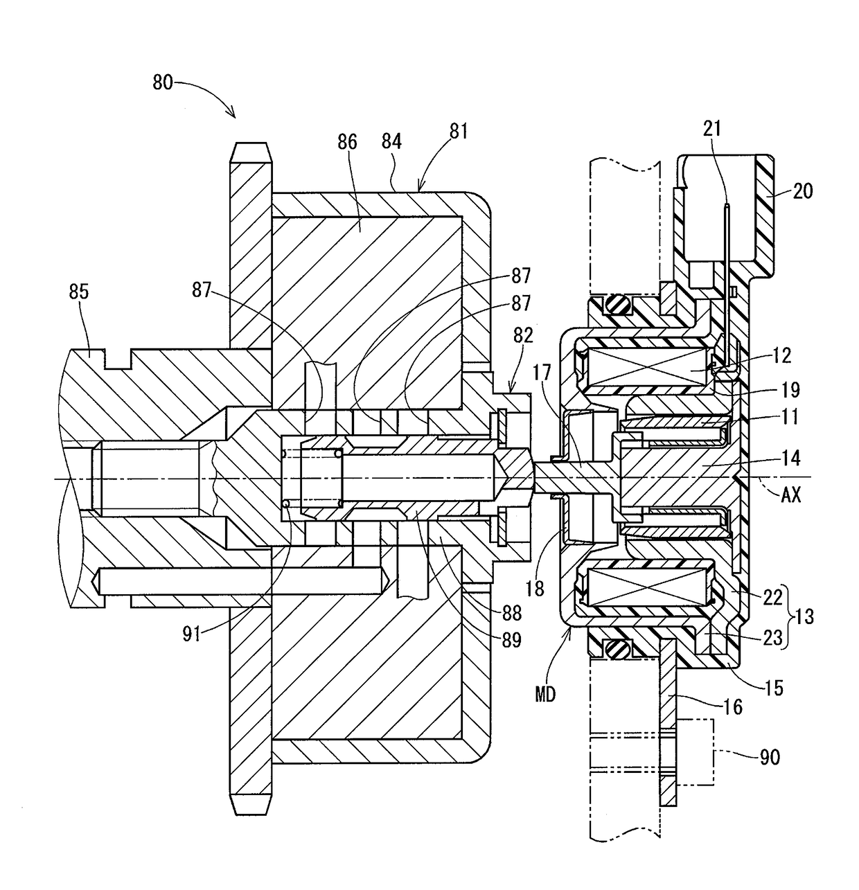
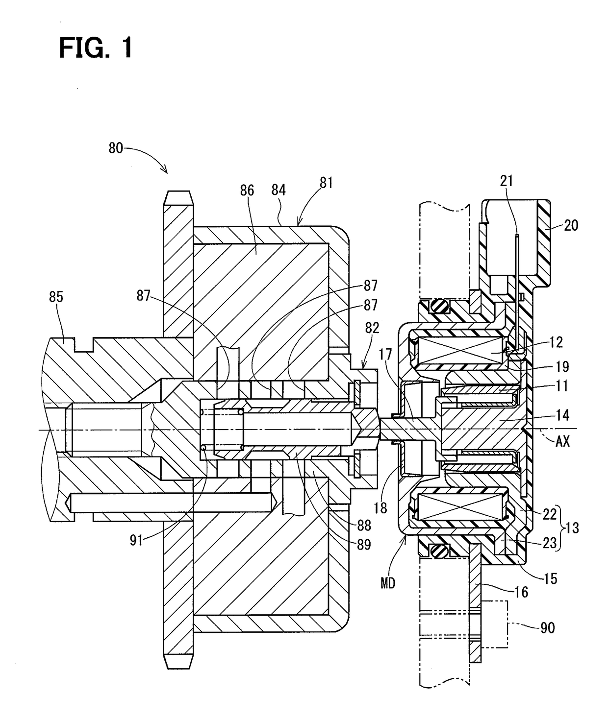
[0036]An electromagnetic actuator according to a first embodiment of the present disclosure is applied to a valve timing adjuster system 80 of an engine shown in FIG. 1. The valve timing adjuster system 80 includes a valve timing adjuster device 81 and an oil pressure control valve 82.

[0037]The valve timing adjuster device 81 includes a housing 84, which is rotated synchronously with a crankshaft of the engine, and a vane rotor 86, which is rotated integrally with a camshaft 85 of the engine. Valve timing of intake valves or exhaust valves of the engine can be adjusted by changing a relative rotational phase between the housing 84 and the vane rotor 86. The vane rotor 86 is rotated relative to the housing 84 according to a degree of an oil pressure of oil pressure chambers (advancing chambers, retarding chambers) formed in an inside of the housing 84. The oil pressure of the oil pressure chambers is adjusted by an oil pressure control valve 82 that is placed at a cen...

Example

Second Embodiment

[0076]In a second embodiment of the present disclosure, as shown in FIG. 8, the outer wall surface 50 is tapered in an axial range, which is from the first proximal end side specific point Pk1 to the first distal end side specific point Ps1. A portion of the outer wall surface 50, which is located on the distal end 44 side of the first distal end side specific point Ps1, is parallel with the axial direction, and another portion of the outer wall surface 50, which is located on the proximal end 43 side of the first proximal end side specific point Pk1, is parallel with the axial direction. Even when the portion of the outer wall surface 50 is tapered, the reduction of the frictional force between the rod 17 and the support tubular portion 32 and the reduction of the amount of swing of the distal end 44 of the rod 17 in the radial direction can be both achieved in comparison to the first and second comparative examples.

Example

Third Embodiment

[0077]In a third embodiment of the present disclosure, as shown in FIG. 9, the outer wall surface 60 is shaped into a stepped form such that the diameter of the rod 17 is reduced in stepwise manner at predetermined intervals from the proximal end 43 side toward the distal end 44 side. The intervals, at each of which the diameter of the rod 17 is reduced, may be freely set. In the present embodiment, the outer wall surface 60 is sequentially stepped in a form of stairs throughout the entire range, which is from the proximal end 43 to the distal end 44. Even with this rod, which is shaped into the sequentially stepped form, the clearance CB, which is formed when the rod 17 is placed in the maximum projected position, is smaller than the clearance CA, which is formed when the rod 17 is placed in the maximum retracted position. Thus, advantages, which are similar to those of the first embodiment, can be achieved.


PUM


Abstract

An electromagnetic drive device includes a through-hole, through which a rod is received, and the rod includes an outer wall surface that is slidable relative to the through-hole. A clearance, which is measured from the outer wall surface of the rod placed in a maximum projected position to an inner wall surface of the through-hole, is smaller than a clearance, which is measured from the outer wall surface of the rod placed in a maximum retracted position to the inner wall surface. Therefore, a retracting-time clearance becomes relatively large, and thereby a frictional force between the rod and a support tubular portion can be reduced. Furthermore, a projecting-time clearance becomes relatively small, and thereby the amount of swing of a distal end of the rod in a radial direction can be reduced.

Description

CROSS REFERENCE TO RELATED APPLICATION[0001]This application is based on and incorporates herein by reference Japanese Patent Application No. 2014-263983 filed on Dec. 26, 2014 and Japanese Patent Application No. 2015-211824 filed on Oct. 28, 2015.TECHNICAL FIELD[0002]The present disclosure relates to an electromagnetic actuator.BACKGROUND ART[0003]There is known an electromagnetic actuator that drives a plunger by a magnetic force generated through energization of a coil to operate an external device through a rod that is formed integrally with the plunger. For example, an electromagnetic actuator of the patent literature 1 is used to operate an oil pressure control valve of a valve timing adjuster device of an engine.[0004]In the patent literature 1, the rod projects from the plunger in an axial direction. An outer peripheral surface of the rod is parallel with a central axis. A yoke forms a support portion that includes a through-hole, through which the rod is received.[0005]When...

Claims


Application Information

Patent Timeline
IPC IPC(8): H01F7/121H01F7/16F16K31/02
CPCH01F7/121F16K31/02H01F7/16F16K31/0613F16K31/0675H01F7/1623H01F2007/086
Inventor NAGASAKA, SHINSUKE
Owner DENSO CORP
Why Eureka
Try Eureka