Image reading apparatus and image forming system

a reading apparatus and reading technology, applied in the direction of electrical apparatus, pictoral communication, etc., can solve the problems of certain limitations in the configuration of the reading section, and achieve the effect of ensuring reading accuracy

Active Publication Date: 2018-09-20
KONICA MINOLTA INC
View PDF3 Cites 2 Cited by
  • Summary
  • Abstract
  • Description
  • Claims
  • Application Information

AI Technical Summary

Benefits of technology

[0010]An object of the present invention is to provide an image reading apparatus and an image forming system that can clean a transmission section provided facing a reading section while ensuring reading accuracy by the reading section.

Problems solved by technology

Accordingly, such a configuration has certain limitations in view of reading accuracy in a reading section.

Method used


Image

  • Image reading apparatus and image forming system
  • Image reading apparatus and image forming system
  • Image reading apparatus and image forming system

Examples


Embodiment Construction

[0030]Hereinafter, one or more embodiments of the present invention will be described with reference to the drawings. However, the scope of the invention is not limited to the disclosed embodiments.

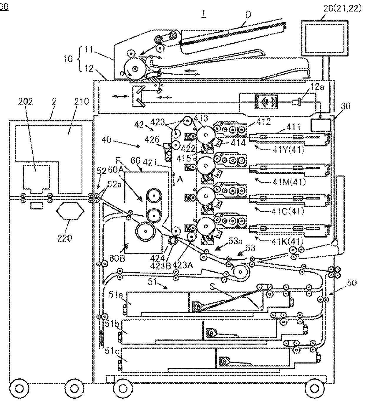
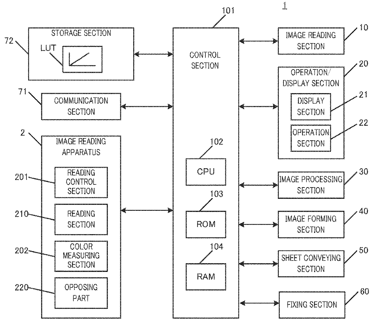
[0031]In the following, the embodiments will be described in detail with reference to the drawings. FIG. 1 schematically illustrates the entire configuration of image forming system 100 of the embodiment. FIG. 2 shows the main part of a control system of image forming apparatus 1 of image forming system 100 according to the embodiment.

[0032]As illustrated in FIG. 1, image forming system 100 includes image forming apparatus 1 and image reading apparatus 2 connected in this order from the upstream side in the conveying direction of sheet S.

[0033]Image forming apparatus 1 is an intermediate transfer-mode color image forming apparatus utilizing electrophotographic process technology. Image forming apparatus 1 transfers color toner images of yellow (Y), magenta (M), cyan (C), and black (K) for...


PUM


Abstract

An image reading apparatus includes a reader, a transmitter, an opposing part that is placed opposite to the transmitter, and a hardware processor that controls a position of the opposing part such that a gap between the transmitter and the opposing part becomes a first gap when images are read by the reader, and a gap between the transmitter and the opposing part becomes a second gap, which is wider than the first gap, when no image is read by the reader.

Description

CROSS REFERENCE TO RELATED APPLICATIONS[0001]The entire disclosure of Japanese patent Application No. 2017-051675, filed on Mar. 16, 2017, is incorporated herein by reference in its entirety.BACKGROUNDTechnological Field[0002]The present invention relates to an image reading apparatus and an image forming system.Description of Related Art[0003]Image forming apparatuses utilizing electrophotographic process technology (printers, copiers, facsimile machines, for example) typically form electrostatic latent images by irradiating charged image bearing members, such as photoconductor drums, with laser beams on the basis of image data. Toner images are then formed by supplying toners from a developing device to the image bearing members, on which the electrostatic latent images have been formed, so as to visualize the electrostatic latent images. Further, the toner images are transferred to sheets directly or indirectly, and then fixed through heating and pressing by a fixing nip, thereby...

Claims


Application Information

Patent Timeline
Patent Type & Authority Applications(United States)
IPC IPC(8): H04N1/028H04N1/00
CPCH04N1/02895H04N1/00952H04N1/0066H04N1/00737H04N1/00779H04N1/00909
Inventor ISOKAWA, HIROSHI
Owner KONICA MINOLTA INC
Why Eureka
Try Eureka