

Rough terrain crane
- Summary
- Abstract
- Description
- Claims
- Application Information
AI Technical Summary
Benefits of technology
Problems solved by technology
Method used
Image

Examples
modification example
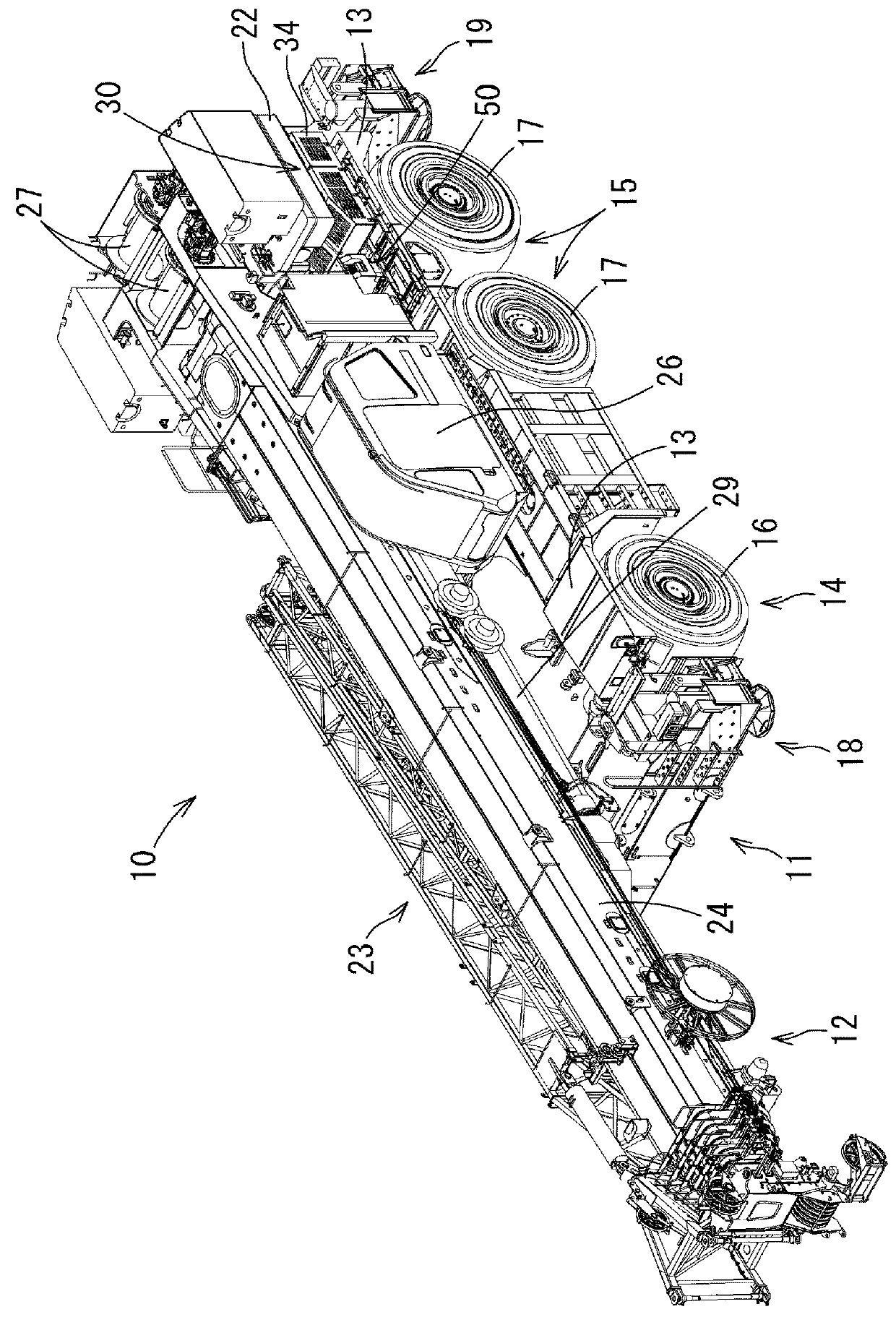
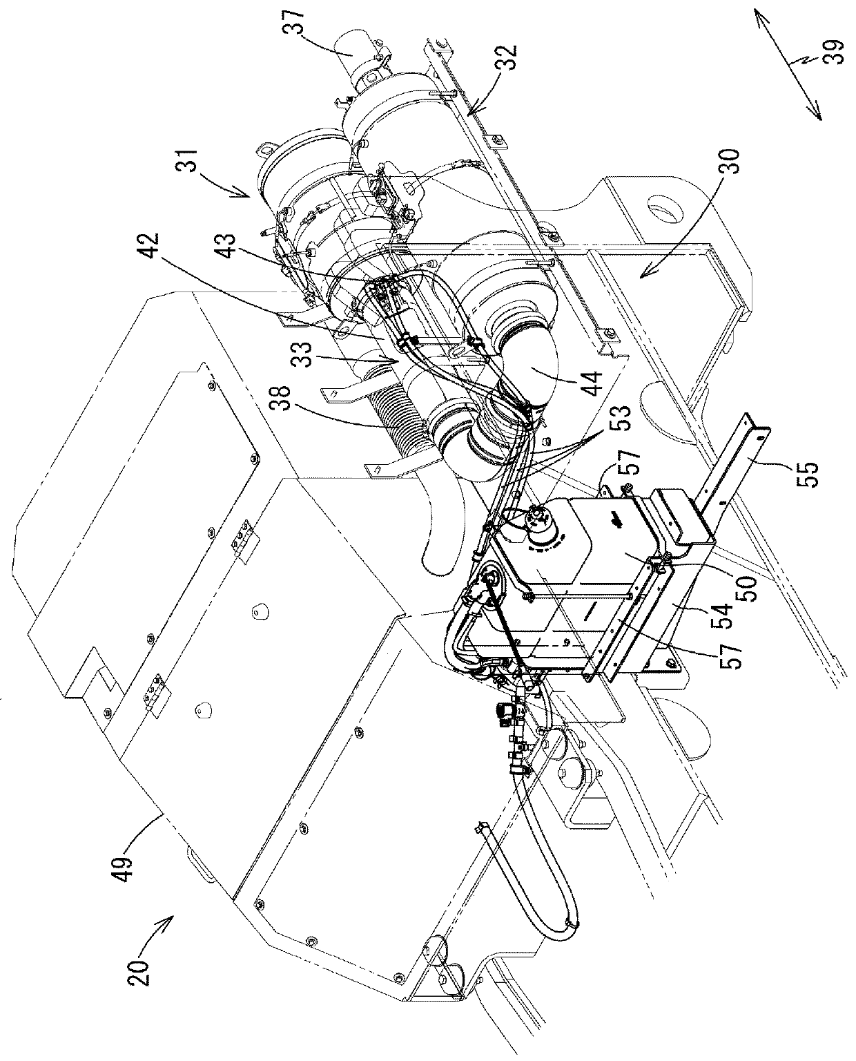
[0058]In the embodiment described above, the urea water tank 50 is disposed at the position illustrated in FIG. 5; however, the position is not limited thereto. For example, as long as the piping of the pipe 53 is allowed to be somewhat complicated, the urea water tank 50 may be disposed on the right side of the diesel engine 20 from the rear direction of the vehicle. In addition, the urea water tank 50 may be disposed in a space between the front axle 14 and the rear axle 15. In short, as long as the urea water tank 50 is positioned at a position at which it is easy to perform the injection work of the urea water and it is easy to receive the impact of the radiation heat from the diesel engine 20, the urea water tank 50 may be disposed at any portion.
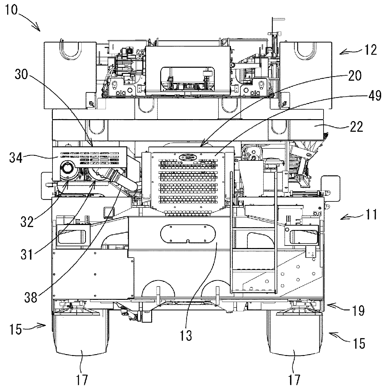
[0059]In the embodiment described above, the exhaust emission control device 30 is disposed at the position adjacent to the left side of the diesel engine 20 when viewed from the vehicle-rear direction as illustrated in FIG. 2; however...
PUM
 Abstract
Description
Claims
Application Information