Molded product processing system

Active Publication Date: 2019-04-11
KIKUSUI SEISAKUSHO LTD
View PDF0 Cites 1 Cited by
  • Summary
  • Abstract
  • Description
  • Claims
  • Application Information

AI Technical Summary

Benefits of technology

The patent describes a system for producing molded products in a containment environment, without external leakage of the atmosphere or damage to the molded products caused by gravity force. The system includes a conveyance mechanism that aligns and shifts the molded products, reducing the risk of damage during transfer. Additionally, the system has a processing mechanism that inspects the molded products for defects and can track and identify the specific components used in the molding process. The technical effects achieved by the system are improved production efficiency, reduced risk of damage to molded products, and improved quality control.

Problems solved by technology

Such a technique obviously causes gradual decrease in height of the molded products and requires disposition of a lift configured to halfway lift upward the molded products.
Furthermore, when the molded products drop onto the chute, the molded products may hit an inner wall or a bottom wall of the chute or may collide with each other to be damaged (e.g., broken, chipped, or abraded).
In particular, molded products having less hardness such as orally disintegrating tablets (OD tablets that disintegrate by saliva or a small amount of water in an oral cavity) or chewable tablets (that are crunched in an oral cavity) are seriously damaged by dropping.
Furthermore, the molded products become not aligned in the order of molding by the compression-molding machine while being transported via the chute.
Upon tableting failure such as sticking of the powdery material kept adhering to a specific one of the die bores or the punches of the compression-molding machine to cause a chipped molded product or mold trouble such as chipping at a tip of one of the punches, a normal molded product and a defective molded product are mixed to be indistinguishable from each other.
A large number of molded products are thus entirely required to be discarded in this case.

Method used


Image

  • Molded product processing system
  • Molded product processing system
  • Molded product processing system

Examples


Embodiment Construction

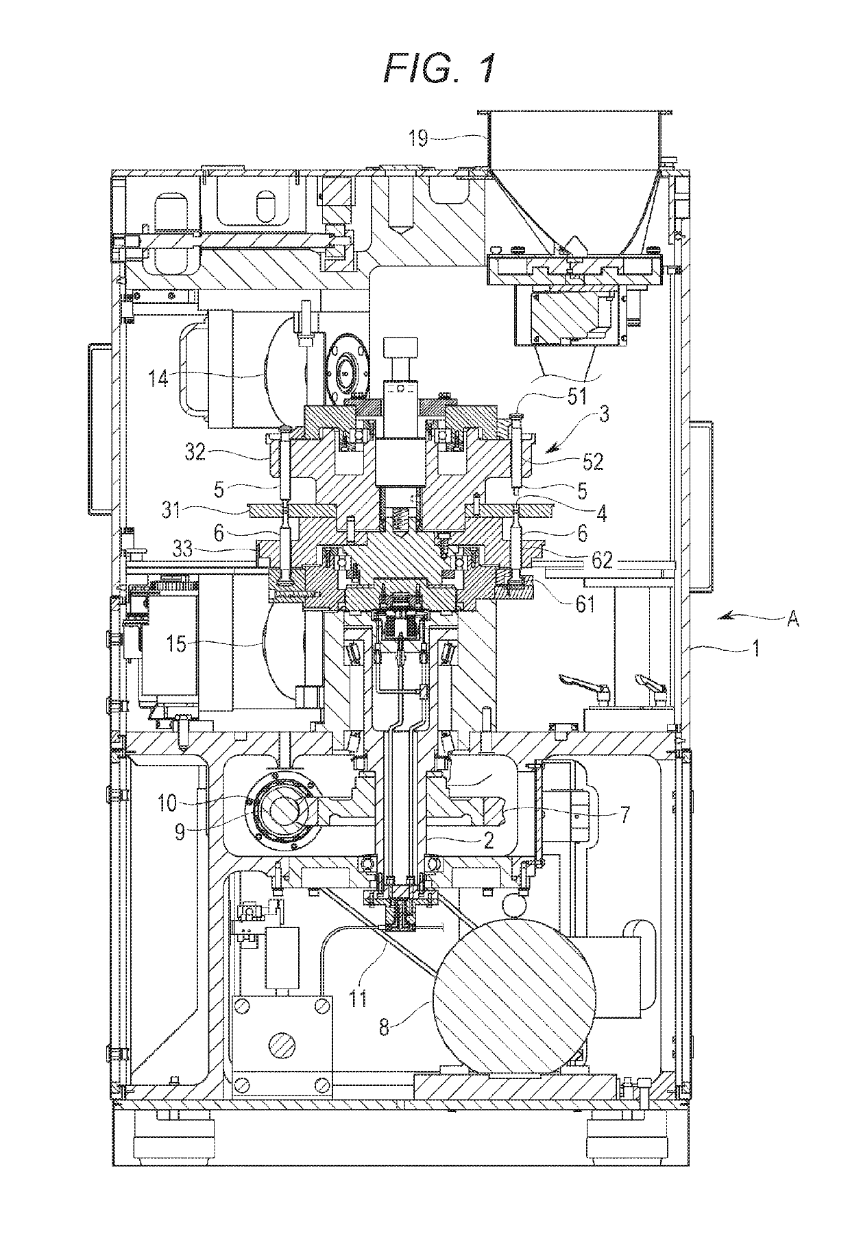
[0034]An exemplary embodiment of the exemplary invention will now be described with reference to the drawings. Initially described is an overview of an entire rotary compression-molding machine (hereinafter, referred to as the “molding machine”) A according to the exemplary embodiment. As shown exemplarily in FIG. 1, the molding machine A includes a frame 1 accommodating an upright shaft 2 functioning as a rotary shaft and a turret 3 attached to a connection portion that is disposed at a top of the upright shaft 2.

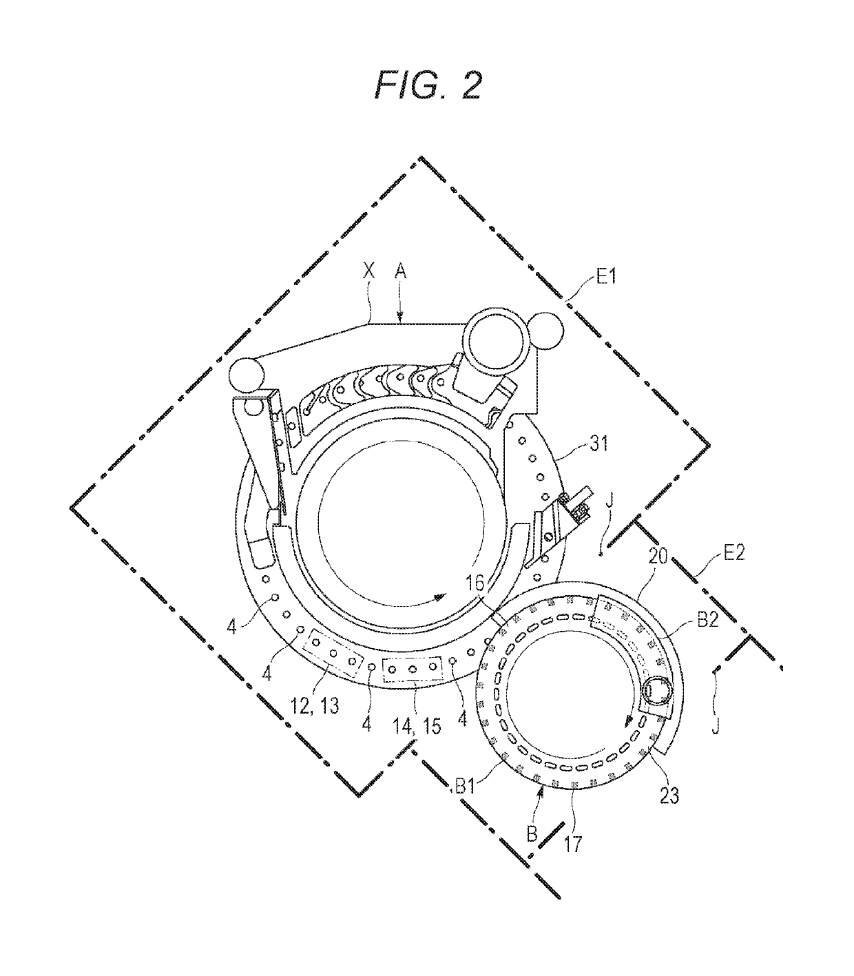
[0035]The turret 3 horizontally rotates about the upright shaft 2, and more specifically, spins. The turret 3 includes a die table (e.g., die disc) 31, an upper punch retaining portion 32, and a lower punch retaining portion 33. As shown exemplarily in FIG. 2, the die table 31 has a substantially circular disc shape in a planar view in a vertical direction, and has a plurality of die bores 4 that is disposed in an outer circumferential portion and is aligned in a rotation ...


PUM


Abstract

A molded product processing system is configured to apply a post process to a molded product molded by a compression-molding machine. The system includes modules each including a conveying mechanism configured to convey a plurality of molded products P kept aligned, and a processing mechanism confronting a travel route of the molded products conveyed by the conveying mechanism and configured to apply a predetermined post process to each of the conveyed molded products, in which upstream one of the modules and downstream one of the modules are connected to allow the molded products having gone through certain processing at the upstream one of the modules to be delivered to the downstream one of the modules and be subjected to a different predetermined processing at one of the modules.

Description

BACKGROUND[0001]There has been known a rotary compression-molding machine including a die table of a turret having die bores, an upper punch and a lower punch slidably retained above and below each of the die bores, and configured to horizontally rotate the die table and the punches together to compression mold (or make a tablet) a powdery material filled in the die bores when the paired upper and lower punches pass between an upper roll and a lower roll. The molding machine of this type is applied, for example, to produce pharmaceutical tablets, food products, electronic components, and the like.[0002]Each molded product is subjected to various post processes. Examples of the post processes include inspecting the molded product as to whether or not the molded product has a defective exterior, removing dust adhering to the molded product, inspecting the molded product in terms of volume, weight, or components, inspecting as to whether or not the molded product contains any alien met...

Claims


Application Information

Patent Timeline
IPC IPC(8): B30B11/10B30B11/00B30B15/26B30B15/00B30B15/02B30B15/30B30B15/32
CPCB30B11/10B30B11/005B30B15/26B30B15/0023B30B15/022B30B15/302B30B15/32B30B11/08B65G47/846B29C43/08
Inventor SHIMADA, SATOSHIKAKITANI, TOMOHIROSUZUKIKUSUNOKI, HITOSHIWATANO, SATORU
Owner KIKUSUI SEISAKUSHO LTD
Why Eureka
Try Eureka