Centrifugal filtering device and method for operating the same

a centrifugal filtering and centrifugal technology, applied in centrifuges, separation processes, filtration separation, etc., can solve the problems of remarkable increase in achieve the effect of reducing work time and production costs, increasing the frequency of replacing or cleaning, and maintaining a stable and high level of filtration ra

Active Publication Date: 2019-08-15
WU JUNG MING
View PDF0 Cites 11 Cited by
  • Summary
  • Abstract
  • Description
  • Claims
  • Application Information

AI Technical Summary

Benefits of technology

[0008]In viewing of the prior art, the conventional centrifugal machine has the particles and the filtrate to move in the same direction, so that the particles would be accumulated on the filter. As a result, the filtration rate is reduced, or frequent replacement or cleaning of the filter is necessary. Accordingly, it is a primary object of the present invention to provide a centrifugal...

Problems solved by technology

Consequently, work time and pro...

Method used


Image

  • Centrifugal filtering device and method for operating the same
  • Centrifugal filtering device and method for operating the same
  • Centrifugal filtering device and method for operating the same

Examples


first embodiment

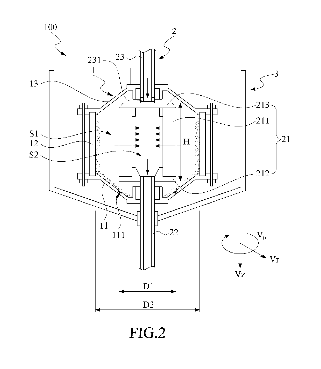
[0032]Referring now to FIG. 2, a schematic view of the centrifugal filtering device in accordance with the present invention is shown. The centrifugal filtering device 100 is applied to filter a source fluid, where the source fluid can include plural types of particles (not labeled in the figure). The centrifugal filtering device 100 includes a centrifugal drum 1, a rotary filter 2 and a fluid-collecting tank 3. The centrifugal drum 1 further includes a lower casing 11, a drum body 12 and a upper casing 13. The lower casing 11 is structured to have a plurality of fluid outlets 111 (one labeled in the figure). The drum body 12 is disposed between the lower casing 11 and the upper casing 13 so as thereby to form internally a receiving space S1. The receiving space S1, defined usually as a tank for a centrifugal machine, can be shaped into, but not limited to, a cylindrical tank, a rectangular tank, a cubic tank or a tank with a shape relevant to a conventional centrifugal machine or a...

sixth embodiment

[0047]Please refer to FIG. 7, a schematic view of the centrifugal filtering device in accordance with the present invention is shown. As shown, The source fluid-feeding pipe 23 has a material-feeding opening 232 laterally extends toward the sidewall of the centrifugal drum 1 to make sure that the heavy-phase fluid may hit the centrifugal drum 1 to force the light-phase fluid moving toward the filter cartridge 211 for mass balance. As a preferred embodiment, the location of the material-feeding opening 232 is defined by the equation D4 / D3>0.4, where D4 is the distance from the rotating axis to the material-feeding opening 232, and D3 is the radius of the centrifugal drum 1, and the equation D4 / D3>0.5 is preferred.

[0048]Refer to FIG. 2 and FIG. 8, where FIG. 8 shows schematically a practical application of the centrifugal filtering device of FIG. 2. as shown, the operation method of the centrifugal filtering device 100 in accordance with the present invention is firstly to construct a...


PUM

PropertyMeasurementUnit
Centrifugal forceaaaaaaaaaa
Speedaaaaaaaaaa
Radiusaaaaaaaaaa

Abstract

A centrifugal filtering device includes a centrifugal drum and a rotary filter. The centrifugal drum has a receiving space for accommodating the source fluid. The rotary filter rotatably mounted in the receiving space includes a filter body and a filtrate discharge pipe. The filter body includes a filter cartridge defining a filtrate-collecting space. The filtrate discharge pipe connecting the filter body is communicative in space with the filtrate-collecting space. By rotating at least one of the centrifugal drum and the rotary filter, the source fluid is driven to generate a vortex by a centrifugal force. The centrifugal force drives the source fluid to form a heavy-phase fluid hitting the centrifugal drum and a light-phase fluid approaching the filter cartridge. The light-phase fluid passes the filter cartridge and then reaches the filtrate-collecting space as a filtrate, and the filtrate is exhausted via the filtrate discharge pipe of the centrifugal filtering device.

Description

CROSS REFERENCE TO RELATED APPLICATIONS[0001]This application is a Continuation-in-Part of co-pending application Ser. No. 15 / 198,866, filed on Jun. 30, 2016, for which priority is claimed under 35 U.S.C. § 120; and this application claims the benefit of Taiwan Patent Application Serial No. 105114163, filed May 6, 2016, and the Serial No. 104121683, filed Jul. 3, 2015, the entire contents of all of which is incorporated herein by reference.BACKGROUND OF INVENTION1. Field of the Invention[0002]The invention relates to a centrifugal filtering device, and more particularly to the centrifugal filtering device that rotates a centrifugal drum or a rotary filter to generate a centrifugal force so as to separate a source fluid into a light-phase fluid and a heavy-phase fluid.2. Description of the Prior Art[0003]Centrifugal methods and filtration technologies are widely applied in various industries such as petrochemicals, metallurgy, chemical engineering, biology, foods, energies, mechanica...

Claims


Application Information

Patent Timeline
IPC IPC(8): B04B3/00B01D33/073B04B11/02B01D17/02B01D33/11
CPCB04B3/00B01D33/073B04B11/02B01D17/0217B01D33/11B04B1/08B04B7/16B04B11/08
Inventor WU, JUNG-MING
Owner WU JUNG MING
Why Eureka
Try Eureka