Centrifugal filtering device and method for operating the same

a centrifugal filtering and centrifugal technology, applied in centrifuges, separation processes, filtration separation, etc., can solve the problems of remarkable increase in achieve the effect of reducing work time and production costs, increasing the frequency of replacing or cleaning, and maintaining a stable and high level of filtration ra

Inactive Publication Date: 2017-01-05
SEVEN JUICE CO LTD
View PDF5 Cites 8 Cited by
  • Summary
  • Abstract
  • Description
  • Claims
  • Application Information

AI Technical Summary

Benefits of technology

[0010]In viewing of the prior art, the conventional centrifugal machine has the particles and the filtrate to move in the same direction, so that the particles would be accumulated on the filter. As a result, the filtration rate is reduced, or frequent replacement or cleaning of the filter is necessary. Accordingly, it is a primary object of the present invention to provide a centrifugal filtering device that utilizes the balancing of the centrifugal force and the mass, in which the centrifugal force drives the particles to move in one direction, while the continuing inlet fluid is driven to move in an opposite direction toward the filter. Thus, the filtration rate can be maintained at a stable and high level, and no more frequent replacing or cleaning the filter is necessary.

Problems solved by technology

Consequently, work time and production cost are increased remarkably.

Method used


Image

  • Centrifugal filtering device and method for operating the same
  • Centrifugal filtering device and method for operating the same
  • Centrifugal filtering device and method for operating the same

Examples


Embodiment Construction

[0032]The invention disclosed herein is directed to a centrifugal filtering device. In the following description, numerous details are set forth in order to provide a thorough understanding of the present invention. It will be appreciated by one skilled in the art that variations of these specific details are possible while still achieving the results of the present invention. In other instance, well-known components are not described in detail in order not to unnecessarily obscure the present invention.

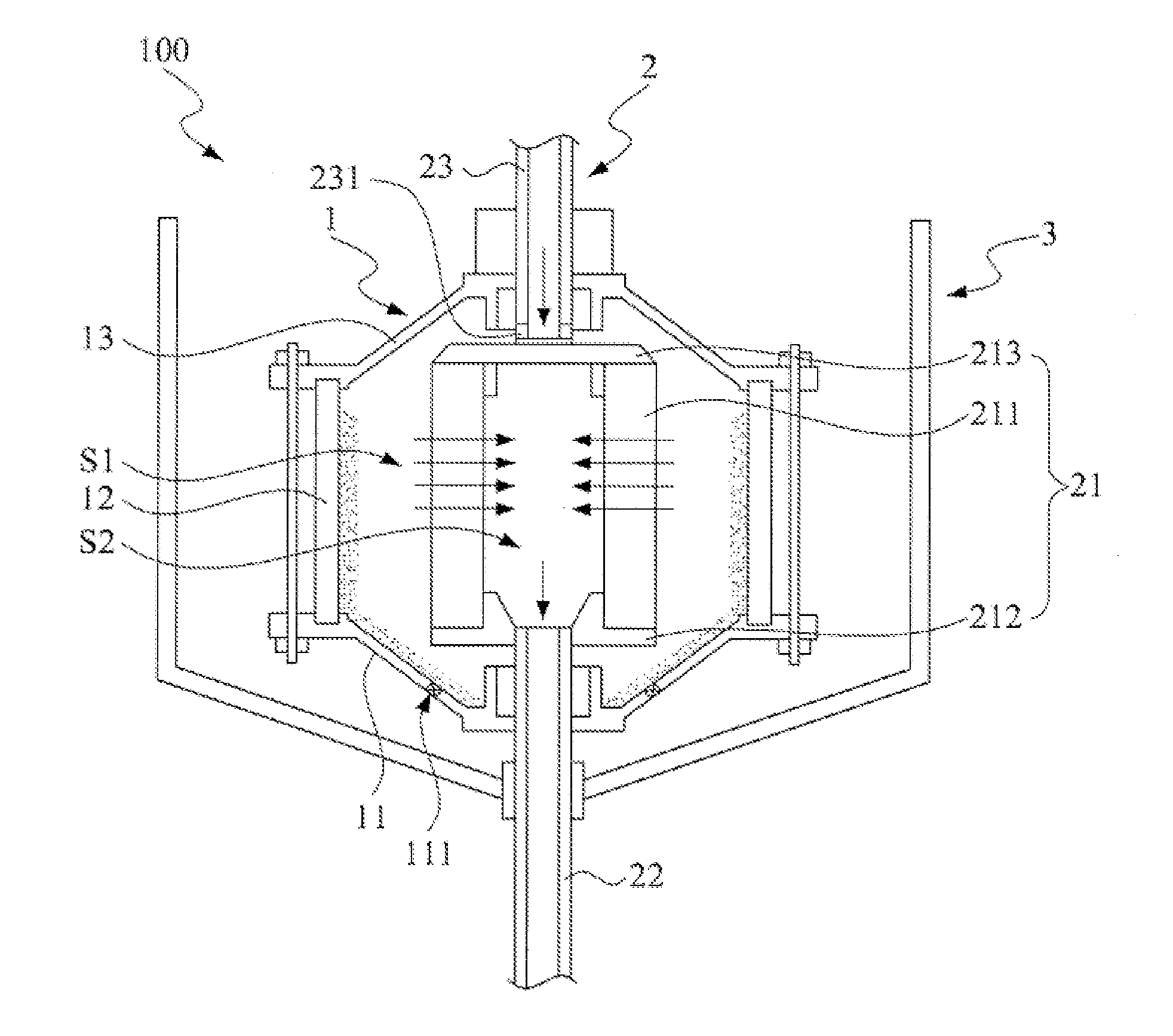
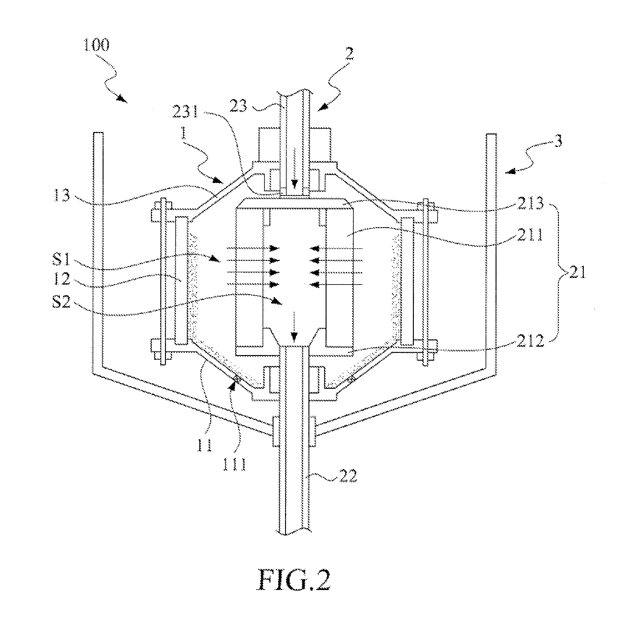
[0033]Referring now to FIG. 2, a schematic view of a first embodiment of the centrifugal filtering device in accordance with the present invention is shown. The centrifugal filtering device 100 is applied to filter a source fluid, where the source fluid can include plural types of particles (not labeled in the figure). The centrifugal filtering device 100 includes a centrifugal drum 1, a rotary filter 2 and a fluid-collecting tank 3. The centrifugal drum 1 further includes a lower ca...


PUM

PropertyMeasurementUnit
centrifugal forceaaaaaaaaaa
weight distributionaaaaaaaaaa
concentrationaaaaaaaaaa

Abstract

A centrifugal filtering device includes a centrifugal drum and a rotary filter. The centrifugal drum has a receiving space for accommodating the source fluid. The rotary filter rotatably mounted in the receiving space includes a filter body and a filtrate discharge pipe. The filter body includes a filter cartridge defining a filtrate-collecting space. The filtrate discharge pipe connecting the filter body is communicative in space with the filtrate-collecting space. By rotating at least one of the centrifugal drum and the rotary filter, the source fluid is driven to generate a vortex by a centrifugal force. The centrifugal force drives the source fluid to form a heavy-phase fluid hitting the centrifugal drum and a light-phase fluid approaching the filter cartridge. The light-phase fluid passes the filter cartridge and then reaches the filtrate-collecting space as a filtrate, and the filtrate is exhausted via the filtrate discharge pipe of the centrifugal filtering device.

Description

[0001]This application claims the benefit of Taiwan Patent Application Serial No. 105114163, filed May 6, 2016, and the Serial No. 104121683, filed Jul. 3, 2015, subject matter of which is incorporated herein by reference.BACKGROUND OF INVENTION[0002]1. Field of the Invention[0003]The invention relates to a centrifugal filtering device, and more particularly to the centrifugal filtering device that rotates a centrifugal drum or a rotary filter to generate a centrifugal force so as to separate a source fluid into a light-phase fluid and a heavy-phase fluid.[0004]2. Description of the Prior Art[0005]Centrifugal methods and filtration technologies are widely applied in various industries such as petrochemicals, metallurgy, chemical engineering, biology, foods, energies, mechanical engineering, power, coals, alcohols, textiles, pharmaceutics, health and the like. Conventional centrifugal apparatuses are used to separate fluids (including a liquid phase, a gas phase and a solid phase in ...

Claims


Application Information

Patent Timeline
Patent Type & Authority Applications(United States)
IPC IPC(8): B04B3/00B01D33/76B04B11/02B01D33/073
CPCB04B3/00B04B11/02B01D33/763B01D33/073B04B7/12B04B7/16B04B15/06
Inventor WU, JUNG-MING
Owner SEVEN JUICE CO LTD
Why Eureka
Try Eureka