
Portable Motor Coil Cutter

A portable and cutter technology, which is applied in the manufacture of motor generators, electromechanical devices, electrical components, etc., can solve the problems of increased maintenance costs, heavy physical exertion of maintenance personnel, and low maintenance efficiency, so as to reduce wear and avoid aggravated cleaning work Effect

Active Publication Date: 2019-12-13
浙江利邦智能传动有限公司
View PDF4 Cites 0 Cited by
  • Summary
  • Abstract
  • Description
  • Claims
  • Application Information

AI Technical Summary

Problems solved by technology

[0003] The motor is generally composed of two main parts, the stator assembly and the rotor. The stator assembly is composed of three parts: the stator core, the stator winding and the frame. The main function of the stator is to generate a rotating magnetic field, and the main function of the rotor is to generate a rotating magnetic field. When the motor is cut by the magnetic force line and then generates (output) current, various problems will occur after the motor is used for a long time. The most common problem is that the stator winding is overloaded and overheated, which causes the winding to burn out. At this time, it is necessary to rewind the new stator winding
[0004] At present, most of the maintenance methods of motor stator windings on the market are completed by manpower. The brief maintenance process is as follows: First, the maintenance personnel take a shovel to cut off the stator winding at one end of the motor, and then use a special maintenance iron rod to insert the punching sheet of the motor. In the slot, the entire stator winding is separated from the machine base, and then a new stator winding is wound. In the actual maintenance process, the process of cutting off the stator winding at one end of the motor with a shovel by the maintenance personnel is cumbersome, and The physical exertion of maintenance personnel is also relatively large, and the maintenance efficiency is very low
[0005] In the prior art, the portable motor coil cutter directly cuts the coil, which causes great wear and tear on the cutting knife and requires frequent replacement of the cutting knife, resulting in increased maintenance costs and poor economic benefits

Method used


Image

  • Portable Motor Coil Cutter
  • Portable Motor Coil Cutter
  • Portable Motor Coil Cutter

Examples


Embodiment

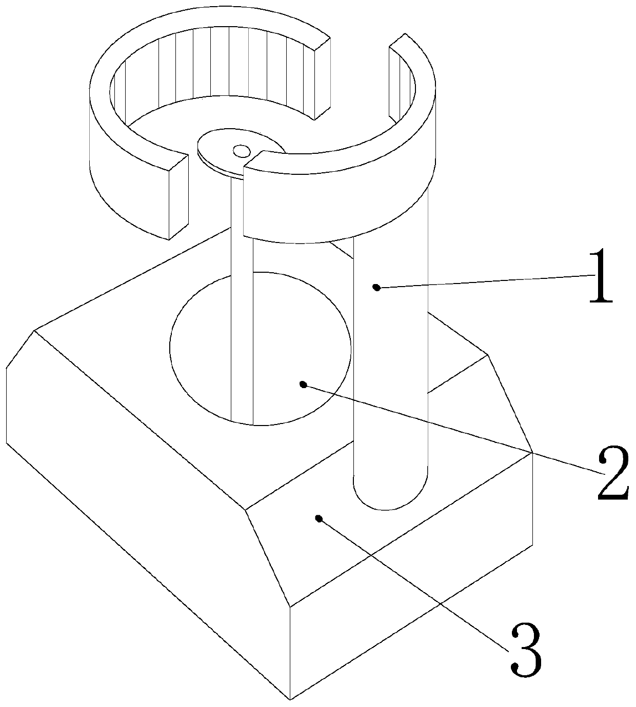
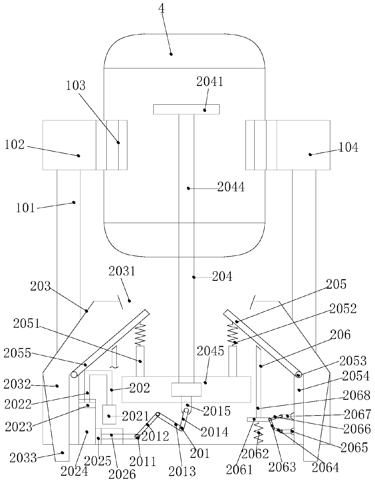
[0028] see Figure 1-Figure 5 , the present invention provides a portable motor coil cutter, its structure includes a motor fixing mechanism 1, a progressive cutting device 2, a fixed base 3, a motor 4, the motor fixing mechanism 1 is mechanically connected to the motor 4, and the motor fixing mechanism 1 Installed on the fixed base 3 and mechanically welded with the fixed base 3, the fixed base 3 is provided with a progressive cutting device 2;

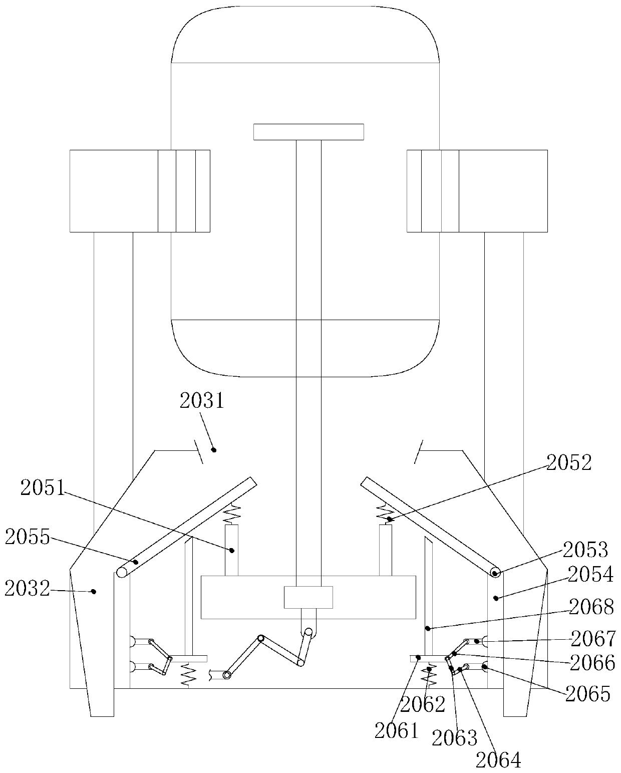
[0029] The progressive cutting device 2 is composed of a mechanical transmission mechanism 201, a cutting device driving mechanism 202, a slag conveying device 203, a cutting device 204, a slag shaking off mechanism 205, and a shock absorbing device 206;

[0030] The mechanical transmission mechanism 201 is mechanically connected with the cutting device driving mechanism 202, the cutting device driving mechanism 202 mechanically cooperates with the cutting device 204 through the mechanical transmission mechanism 201, and the debris s...


PUM


Abstract

The invention discloses a portable motor coil cutter. The portable motor coil cutter structurally comprises a motor fixing mechanism, a progressive cutting device, a fixed base and a motor. The motorfixing mechanism is mechanically connected with the motor, and the motor fixing mechanism is mounted on the fixed base and mechanically connected to the fixed base in a welded mode. The progressive cutting device is arranged in the fixed base. The portable motor coil cutter can control a cutting knife to cut a motor coil in a rotationally progressive mode through the combined action of the motor fixing mechanism, a mechanical transmission mechanism, a driving mechanism of a cutting device, a shred residue conveying device, the cutting device, shred residue shaking-off mechanisms and a shock absorption device, so that the abrasion of the cutting knife can be reduced while the coil is cut off, and generated shred residues after cutting can be collected and uniformly discharged to avoid aggravating the cleaning work.

Description

technical field [0001] The invention relates to the field of cutting equipment, in particular to a portable motor coil cutter. Background technique [0002] Motor refers to an electromagnetic device that converts or transmits electrical energy according to the law of electromagnetic induction. Its main function is to convert electrical energy into torque. [0003] The motor is generally composed of two main parts, the stator assembly and the rotor. The stator assembly is composed of three parts: the stator core, the stator winding and the frame. The main function of the stator is to generate a rotating magnetic field, and the main function of the rotor is to generate a rotating magnetic field. When the motor is cut by the magnetic force line and then generates (output) current, various problems will occur after the motor is used for a long time. The most common problem is that the stator winding is overloaded and overheated, which causes the winding to burn out. At this time...

Claims


Application Information

Patent Timeline
Patent Type & Authority Patents(China)
IPC IPC(8): H02K15/00
CPCH02K15/0006
Inventor 刘施文
Owner 浙江利邦智能传动有限公司
Learn More