Process of laying floorboards

a technology of floorboards and laying boards, which is applied in the field of laying floorboards, can solve the problems of damage to the tongue and groove joint, the risk of the tongue splitting off or the groove breaking apart, and the first procedure described is quite complicated to execute, so as to reduce the risk of damaging the edge, reduce the risk of splitting off or the groove breaking apart, and reduce the risk of damag

Inactive Publication Date: 2004-03-30
KRONOTEX USA
View PDF18 Cites 151 Cited by
  • Summary
  • Abstract
  • Description
  • Claims
  • Application Information

AI Technical Summary

Benefits of technology

The procedure to which the intention refers requires the faces inserted into one another to be shifted in relation to one another only over a short distance, thus minimising friction (the surface subject to friction increases linearly as the "threading" of the tongue and groove proceeds). The force required to overcome the increase in friction can be exerted by hand without the aid of a tool, so that the risk of damaging edges is permanently eliminated.

Problems solved by technology

The first procedure described is quite complicated to execute because the person laying the floor must use one hand to swing the boards up and use the other to push in the new board which is tilted.
If the new board is twisted, there is a risk of the tongue splitting off or of the groove breaking apart.
The mere deadweight of a board can cause damage to the tongue and groove joint when the boards are lifted from the floor.
This means, essentially, that this laying procedure can only be carried out by two persons.
Providing such a tolerance at the joint has, however, the disadvantage that the boards can be shifted not only along the line of the joint but also transversely to it.
In consequence, the attachment between adjoining boards is not moisture-proof and moisture can penetrate.
This is a particular problem in the case of MDF (medium density fibreboard) or HDF (high density fibreboard) laminated boards because there is a risk of the core swelling because of moisture penetration, which can ruin a floor.
This step of course complicates the floor laying procedure.
In addition, ensuring that the joints stay really moisture-proof requires an exact method which cannot be expected when "snap-on interfaces" of this kind are used by home handymen.
Two boards longitudinally jointed together with pre-stressing and measuring several metres in length can, because of friction at the joint, be shifted in relation to one another only with a considerable expenditure of energy.
A careless hammer blow may not only ruin the transverse side of the new board, made fragile by the interface, but also cause damage to the upper edge of the joint which may not be noticed.
If, as a result of such damage to the plane of separation, the boards can no longer be laid tightly, moisture can subsequently penetrate and ruin the floor as described above.
The laying procedure described in the document does not permit the person laying the floor to joint the narrow sides first and then hammer the board on its longitudinal side so as to drive it far enough transversely for it to engage on its longitudinal side with the row of boards previously laid.

Method used


Image

  • Process of laying floorboards
  • Process of laying floorboards

Examples


Embodiment Construction

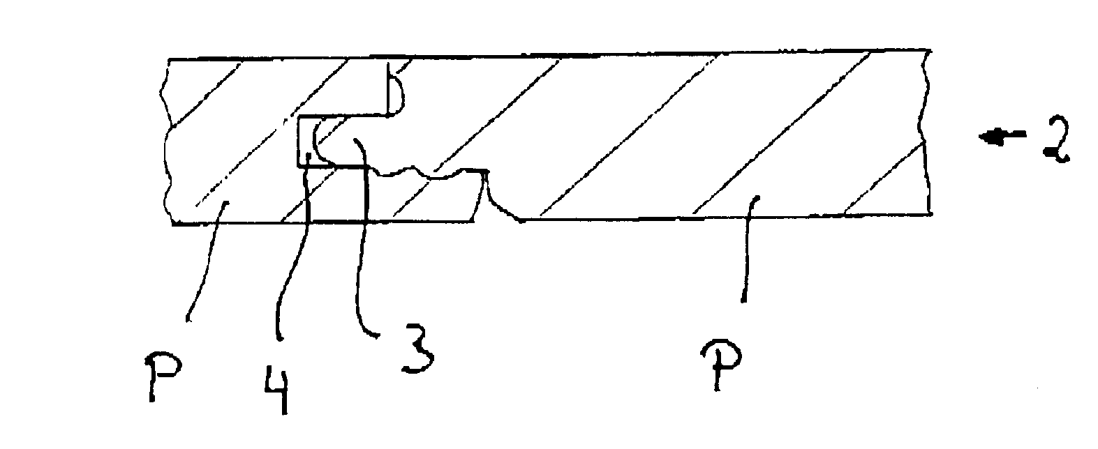
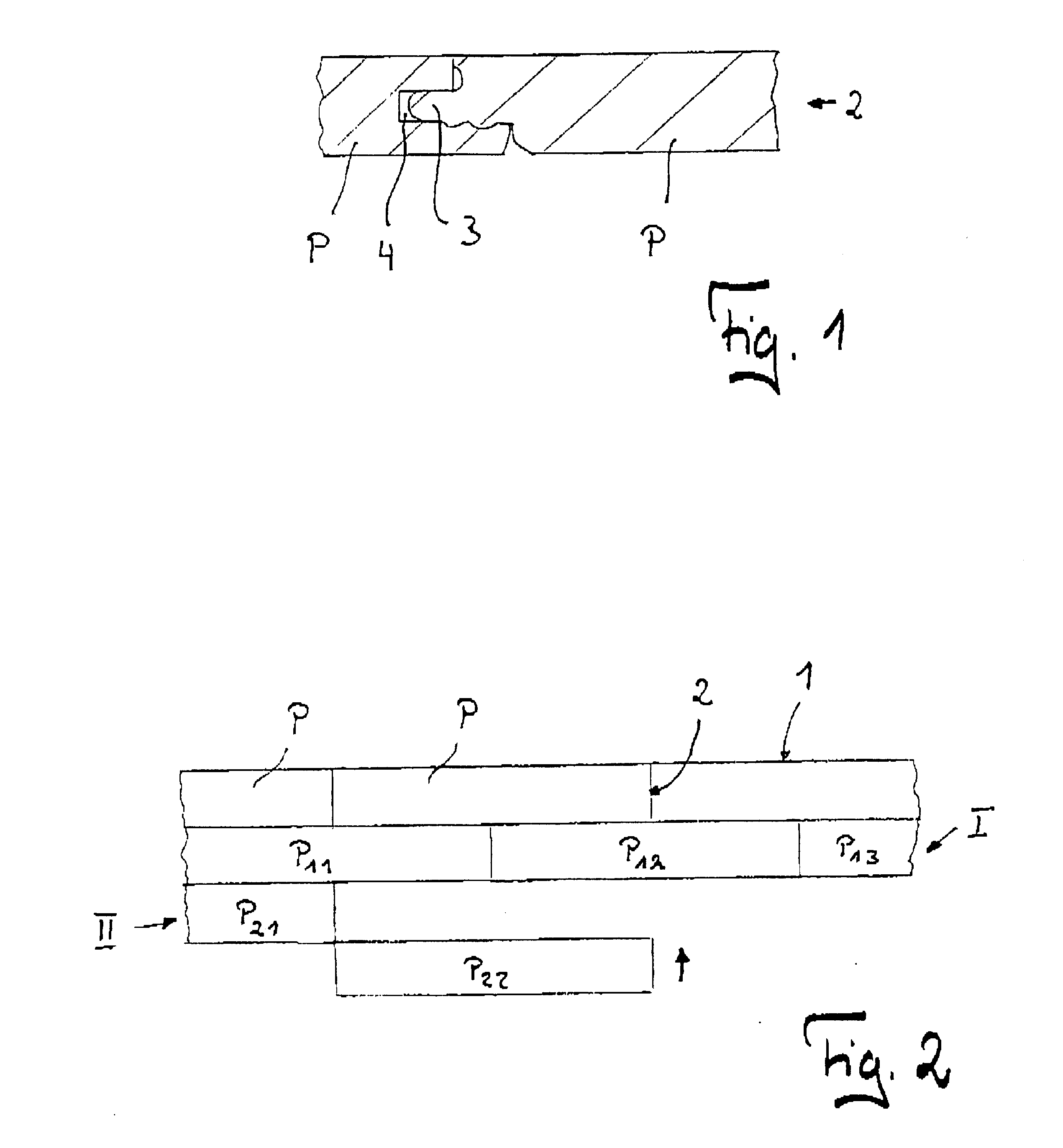
As shown in the accompanying drawings, the boards P have on their longitudinal sides 1 and their transverse sides 2, tongues 3 and grooves 4 in matching opposite positions. On the underside of the tongue 3 there are projections, not described here in further detail, which can engage in recesses, also not described here in further detail, on the lower lip of the groove 4. The boards P can be locked together by pushing the tongue 3 into the groove 4. The constructional details of the boards will not be further explained. In this regard, reference may be made to German patent No. 198 21 200.

For the purpose of laying the floor, the first step is to make a first row I of boards P.sub.11, P.sub.12, P.sub.13, . . . P.sub.1n from wall to wall of a room, these boards P.sub.11, . . . P.sub.1n being jointed on their transverse sides. In a following row II, a first board P.sub.21 is jointed on its longitudinal side with the first board P.sub.11 in the previously laid first row I. A board P.sub....


PUM

PropertyMeasurementUnit
densityaaaaaaaaaa
swellingaaaaaaaaaa
lengthaaaaaaaaaa

Abstract

A process is proposed for laying and mechanically jointing floorboards provided with tongue and groove engagements on all sides for horizontal attachment. The process involves a) jointing of a number of boards and making them engage on their transverse sides n order to lay a first row on the floor of a room, b) jointing of a first board for a second row and making it engage with one or two boards in the first row using the tongue and groove joint on the longitudinal side for the purpose of starting a second row, c) pushing the tongue (or groove) of a second board into the groove (or tongue) on the transverse side of the first board in the second row, with movement from the longitudinal side towards the boards in the first row, and d) making the second board engage with one or two boards in the first row.

Description

This invention refers to a process of laying and mechanically jointing floorboards which have a tongue one of their longitudinal and transverse sides and a groove matching the tongue on their opposite longitudinal and transverse sides, the tongue and groove being designed to permit boards to engage with one another horizontally.A number of floorboard-laying procedures are described in U.S. Pat. Nos. 5,860,267 and 6,023,907. In the known procedures, the boards are placed in an initial row and at least one board is placed in the second row and is jointed on its longitudinal side to boards in the first row. A new board is partially jointed on its transverse side to the board in the second row. The new board is placed flat on the floor. The board from the second row and the new board are then lifted together and tilted against the first row. The new board is then shifted relatively to the board from the second row until it engages on its longitudinal side with boards in the first row.Th...

Claims


Application Information

Patent Timeline
Patent Type & Authority Patents(United States)
IPC IPC(8): E04F15/04E04F15/02
CPCE04F15/04Y10T428/14E04F2201/0115Y10T428/2395
Inventor TYCHSEN, DETLEF
Owner KRONOTEX USA
Why Eureka
Try Eureka