Ceiling interface for luminaires

a luminaire and interface technology, applied in the field of mounting systems, can solve the problems of cumbersome replacement and/or replacement of luminaires, difficult to perform further changes in lighting solutions, and achieve the effect of removing luminaires

Active Publication Date: 2020-03-19
SIGNIFY HLDG BV
View PDF0 Cites 0 Cited by
  • Summary
  • Abstract
  • Description
  • Claims
  • Application Information

AI Technical Summary

Benefits of technology

[0044]When installed, in embodiments it may be possible to remove the luminaire, such as by twisting the luminaire out of the ceiling with the necessary torque.

Problems solved by technology

However, further changes in the lighting solutions, like installing additional luminaires or replacing luminaires, may be hard to perform.
Problems with solutions may e.g. be that installed ceiling luminaires require access from the top side when the luminaires need to be serviced, or replaced, which presently renders said replacement and / or servicing cumbersome.

Method used


Image

  • Ceiling interface for luminaires
  • Ceiling interface for luminaires
  • Ceiling interface for luminaires

Examples


Embodiment Construction

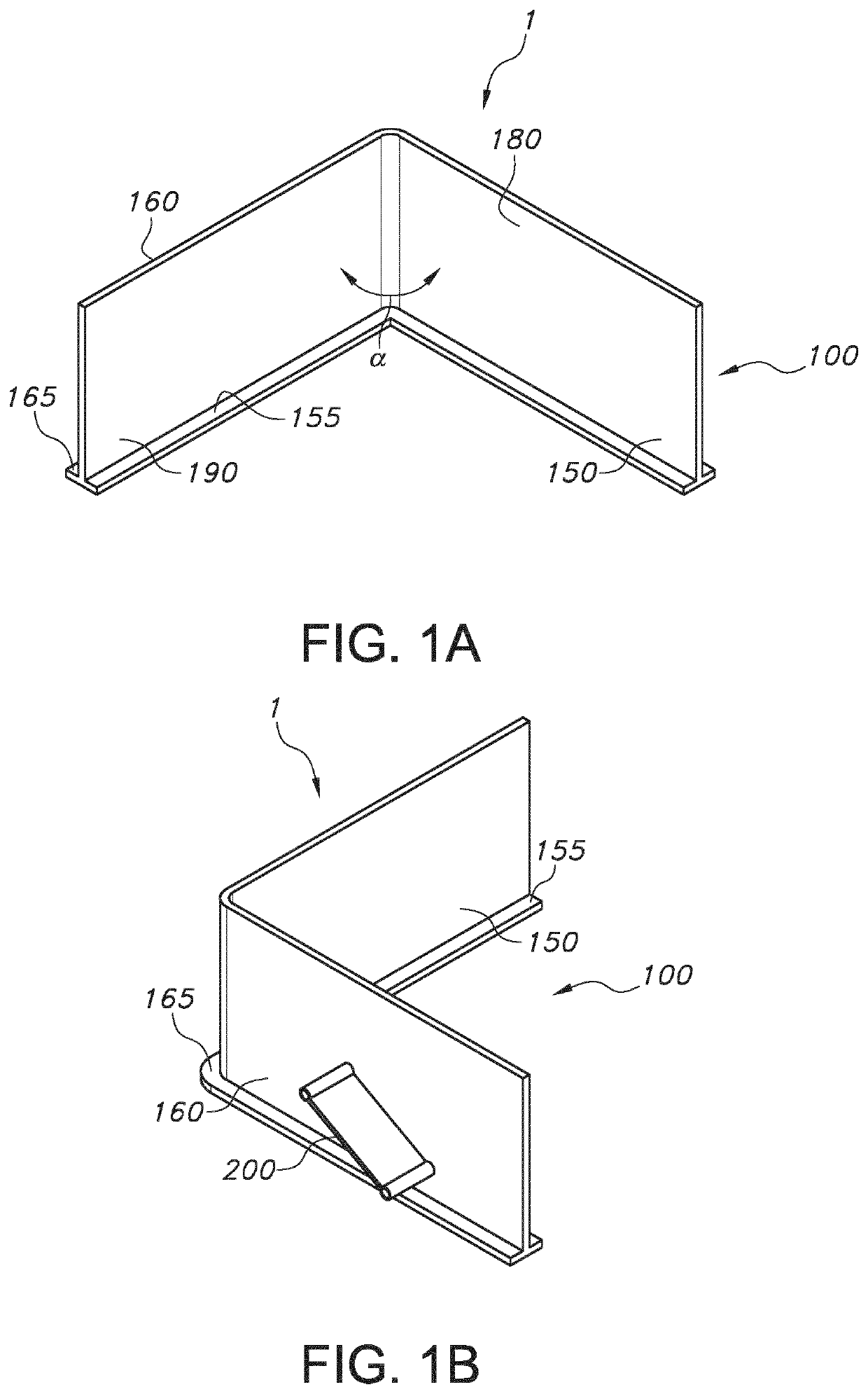
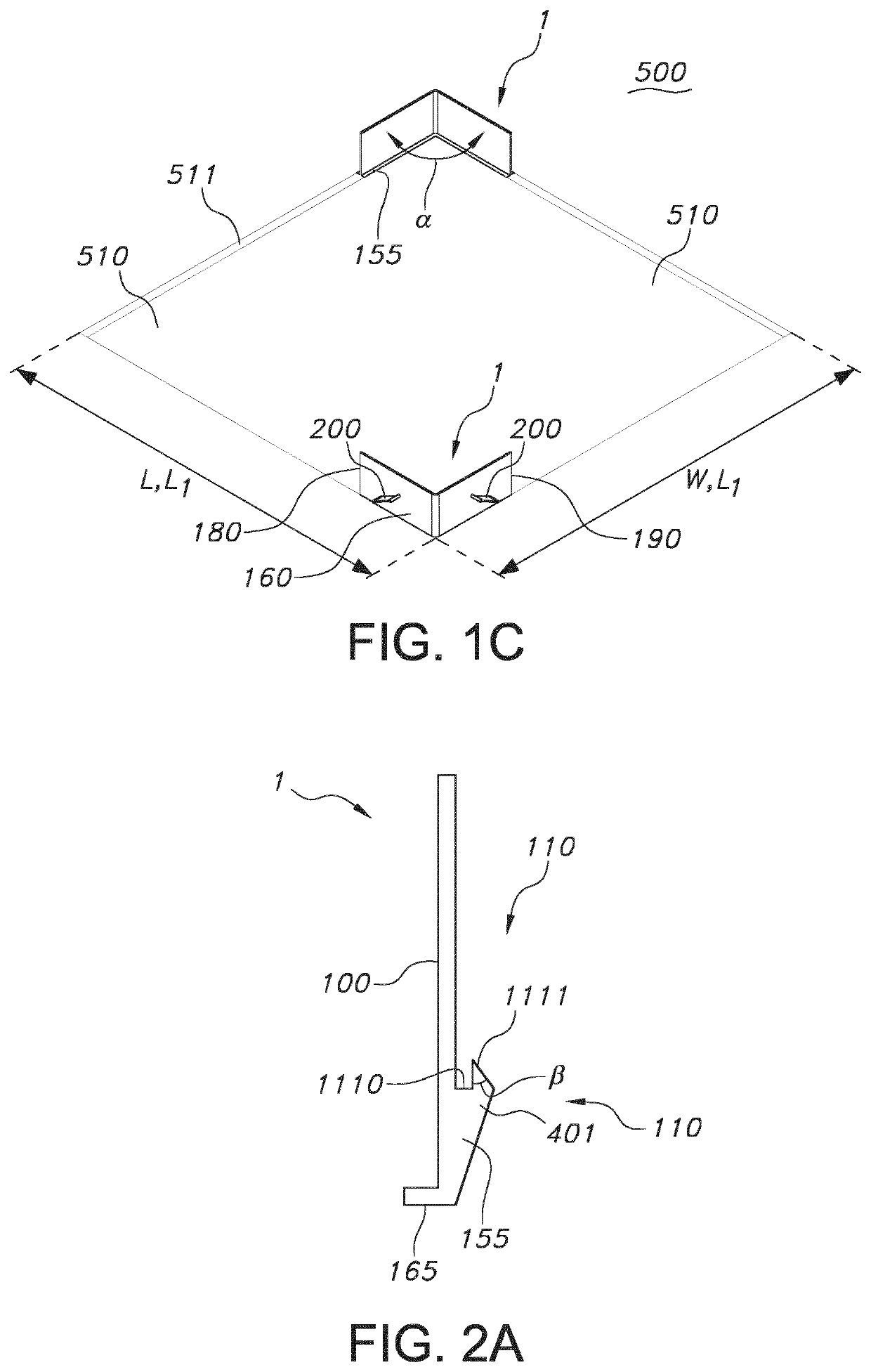
[0052]In FIGS. 1a-1c some aspects of embodiments of the fixture element 1 are schematically depicted. The fixture element 1 may be used for mounting a luminaire 10 at least partly in an opening 510 of a ceiling 500. The fixture element 1 comprises a body 100, two side portions 155, 165, and an engagement element 200. The first side portion 155 protrudes relative to the body 100 at a first side 150 of the body 100. The second side portion 165 protrudes relative to the body 100 at a second side 160 of the body 100. The engagement element 200 is resiliently connected to the second side 160 of the body 100.

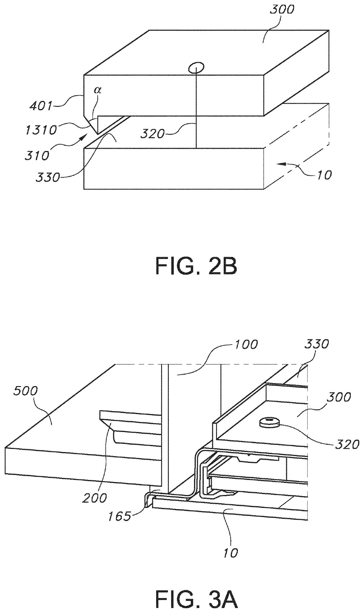
[0053]The first side portion is especially configured to support the luminaire 10. The second side portion is especially configured to contact the ceiling 500, especially to be arranged below the ceiling 500. The engagement element 200 is configured to clamp a part of the ceiling 500 between the engagement element 200 and the second side portion 165, see also FIGS. 3a-3b. For that, th...


PUM


Abstract

The invention provides a fixture element (1) for mounting a luminaire (10) at least partly in an opening (510) of a ceiling (500), wherein the fixture element (1) comprises (i) a body (100), (ii) a first side portion (155) protruding relative to the body (100) at a first side (150) of the body (100) and configured to support the luminaire (10), (iii) a second side portion (165) protruding relative to the body (100) at a second side (160) of the body (100), and (iv) an engagement element (200) resiliently connected to the second side (160) of the body (100) and configured to clamp a part of the ceiling (500) between the engagement element (200) and the second side portion (165).

Description

FIELD OF THE INVENTION[0001]The invention relates to a mounting system, especially a fixture element, and a kit of parts for mounting a luminaire in a ceiling. The invention further relates to a method for mounting a luminaire at (or in) a ceiling.BACKGROUND OF THE INVENTION[0002]Systems for mounting luminaires are known in the art. US 2013 / 0128558, for instance, describes amongst others a lighting fixture that includes a housing formed from walls that are connected by corner posts that are inserted into the ends of the walls and eliminate light leaks and external fasteners. The corner posts include barbs or screw holes for receiving screws from the inside of the walls. The housing can be used as a retrofit for a recessed lighting fixture where the housing can surround the lighting fixture and attach thereto. The assembly can then be mounted by a suitable support.SUMMARY OF THE INVENTION[0003]The major part of in-door lighting solutions has an interface with a ceiling. Because many ...

Claims


Application Information

Patent Timeline
Patent Type & Authority Applications(United States)
IPC IPC(8): F21V21/04F21S8/02
CPCF21S8/026F21V21/044F21V21/043F21V21/049F21V21/041F21V21/042
Inventor GIELEN, VINCENT STEFAN DAVIDNIJKAMP, RICK GERHARDUS
Owner SIGNIFY HLDG BV
Why Eureka
Try Eureka