Lay-in tile speaker system

a speaker system and tile technology, applied in the field of loud speaker systems, can solve the problems of high manufacturing cost, complicated assembly, and clear speaker, and achieve the effect of improving acoustics and maximising free air spa

Inactive Publication Date: 2010-01-05
LOWELL MFG
View PDF21 Cites 6 Cited by
  • Summary
  • Abstract
  • Description
  • Claims
  • Application Information

AI Technical Summary

Benefits of technology

[0008]To accomplish the foregoing and other objects of the present invention there is provided a lay-in tile type of speaker support system for use with suspended ceilings. The system may support various sizes and types of speakers, such as foreground music, sound masking, or paging systems. The system includes a speaker support base that is perforated to improve acoustics by providing maximum free air space. The perforated surface also helps the appearance of the new system to visually blend in with the overall suspended ceiling in which the system is installed. The system further provides integral flanges that form a T-shaped member, when viewed in section, to support at least a portion of a ceiling tile cut to complete to ceiling grid opening. In one embodiment the base and the flanges are constructed from a single sheet of material that is folded to form the flanges. A preferably substantially solid support plate may be utilized to strengthen the base. When the support plate is utilized it is placed against the base and the speaker is mounted to the support plate. The speaker can be mounted with or without a back box. The base is sized to fit within at least a portion of a conventional ceiling tile grid opening, and has substantially ninety degree corners so that the ceiling grid opening is completed by a ceiling tile cut to size with a simple, straight cut.
[0009]In one embodiment the base occupies about one half of the ceiling grid opening and the cut ceiling tile completes the other half of the grid opening. In another embodiment the base occupies about one quarter of the ceiling grid opening and the cut ceiling tile occupies about three quarters of the ceiling grid opening. If desired, the new system can also be sized to fill a complete ceiling tile opening. So, it can be readily seen that the new system offers a great degree of flexibility to the art of ceiling speaker installation.
[0011]A lay-in tile type system is disclosed for supporting speakers in a new or existing suspended ceiling includes a perforated base section providing maximum free air space. A perforated surface also helps the lay-in tile system blend in with the overall suspended ceiling in which the system is installed. The system further provides integral flanges that form a T-shaped member (in section) to support at least a portion of an adjacent ceiling tile, obviating the need to purchase, cut and install a replacement grid member. The base and its side flanges are constructed from a single sheet of material that is folded to form the side flanges, with a section of L bar having an offset at each end and which is fixed to one long edge, adjacent an upstanding guide flange of the support base to guide the positioning of a piece of ceiling tile within a ceiling grid. The base is sized to fit within a portion of a conventional ceiling tile grid opening, and has substantially ninety degree corners so that the ceiling grid opening is completed by a ceiling tile sized with a simple straight cut, simplifying installation.

Problems solved by technology

This is a time consuming and often difficult procedure that results in the speaker being clearly visible in the ceiling.
Unfortunately, due to the complexity of these systems, they tend to be costly to manufacture, complicated to assemble and thus timely and expensive to install.
These systems often require multiple or intricate cuts to the ceiling tile and / or consist of multiple piece supports that must be assembled during installation.

Method used


Image

  • Lay-in tile speaker system
  • Lay-in tile speaker system
  • Lay-in tile speaker system

Examples


first embodiment

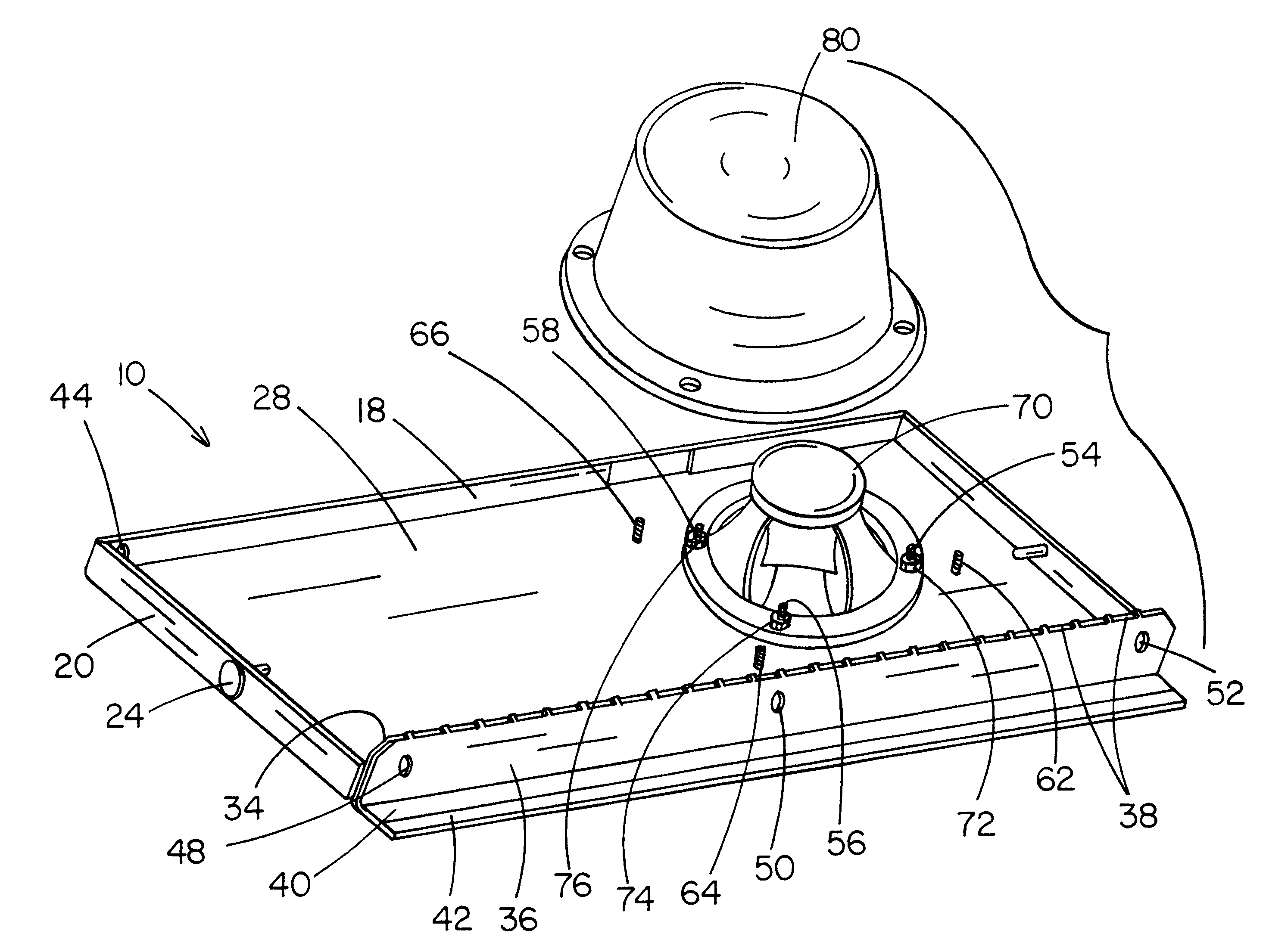
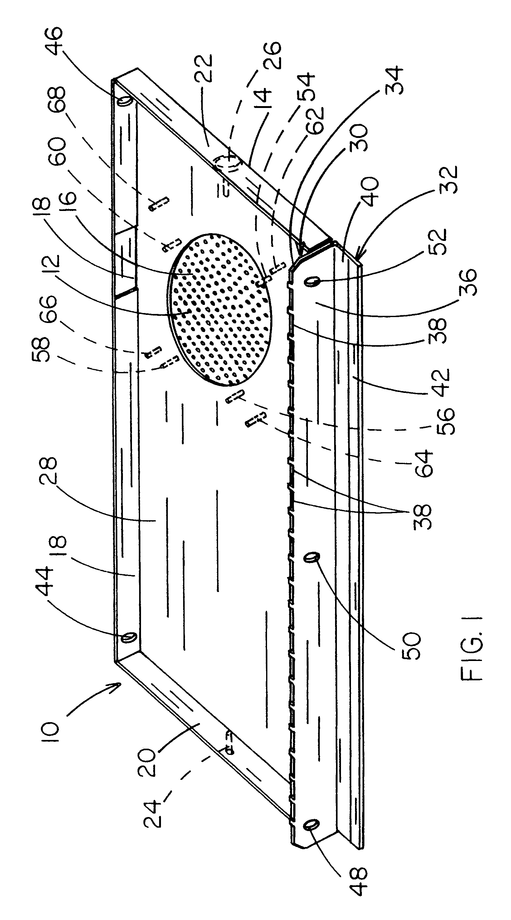
[0032]Support flange 32 includes a support section 40 that intersects and is transverse to flange section 36 and is substantially planar with base 12 and a reinforcement strip 42. In the first embodiment shown in FIGS. 1-10, flanges 18 and 30 include holes 44, 46, 46 and 48, 50, 52 respectively. These holes allow system 10 to be wired or otherwise secured to the building if desired or if required by code.

[0033]Plate 28 provides a solid surface for the installation of one or more speakers, for example 8″ coaxial, 8″ dual cone, or 4″ high compliance driver with 70V or 25 / 70V transformer. Plate 28 includes speaker anchoring bolts 54, 56, 58 and 60 and back box anchoring bolts 62, 64, 66 and 68. As is illustrated in FIG. 9, a speaker 70 is mounted to plate 28 at the bolts and secured in place with nuts 72, 74, 76 and 78 (not shown). A back box 80 is optionally mounted over the speaker 70 and secured by nuts 82, 84, 86 and 88 (not shown).

[0034]System 10 is shown in FIG. 10 installed into...

second embodiment

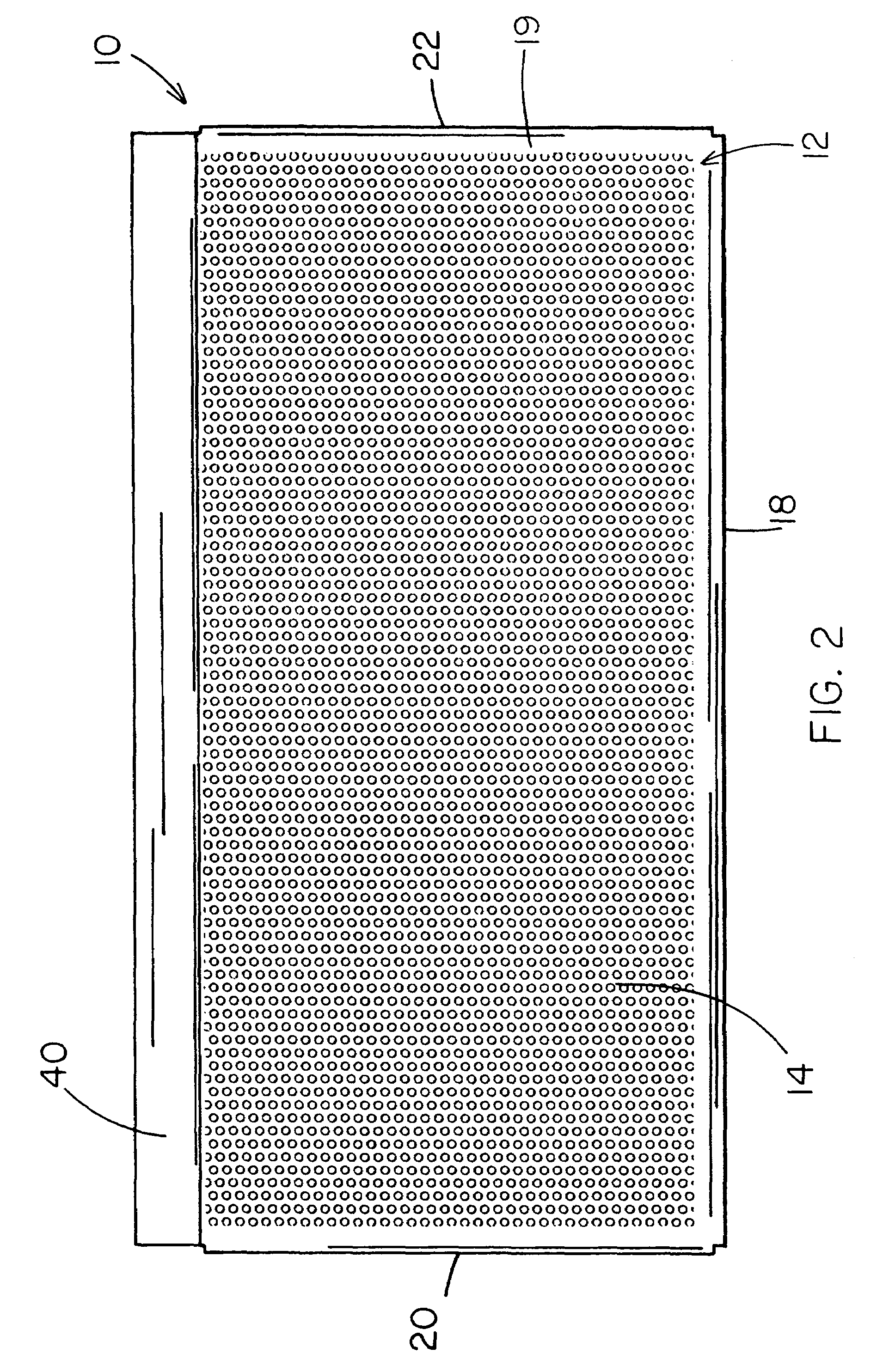
[0035]FIGS. 11, 12 and 13 illustrate a further embodiment of the new speaker support system generally designated 100, which system 100 functions generally the same way and has similar advantages to the embodiment described above, but which varies slightly in its construction. Other than as described below, the second illustrated embodiment is, for the most part, formed and used in substantially the same manner as the first. Thus, elements of the embodiment of FIGS. 11-13 that are the same or provide the same overall structural role as those of the embodiment of FIGS. 1-10 are provided with the same element number, but with the additional prime (′) symbol. The main difference in the second embodiment shown is that the speaker support base 12′ is formed of a sheet of material which is entirely or nearly entirely perforated, rather than material that is only centrally perforated but solid around its periphery, as in the first shown embodiment. This provides a great savings in time of m...


PUM


Abstract

A speaker support system is adapted for use in a suspended ceiling with grid openings and ceiling panels. The system has a speaker support base capable of supporting at least one speaker within a ceiling opening without interfering with the operation of the speaker. A guide flange is integral to the speaker support base and is adapted to align at least a portion of a ceiling tile within the grid opening. A support flange having an offset at each end is integral to the system, connected to the guide flange, and supports at least a portion of the ceiling tile within the ceiling grid opening so that the opening is filled with the speaker support base and the remaining portion of the opening is filled with ceiling tile. The base and guide flange are formed from a single piece of material, which is perforated substantially to at least some of the edges thereof.

Description

CROSS-REFERENCE TO RELATED APPLICATION[0001]This application is a continuation-in-part and claims priority of pending U.S. Ser. No. 09 / 972,465, filed Oct. 5, 2001.BACKGROUND OF INVENTION[0002]This invention relates generally to a loud speaker system and more particularly to a speaker support system for use in a new or existing conventional suspended ceiling, which system includes an integral t-shaped flange to thereby facilitate installation of the system.[0003]Suspended ceilings are typically constructed of a suspended metal grid, the grid having ceiling grid openings into which acoustic tiles or panels are assembled to create the ceiling. Often it is desired to include a speaker system within the ceiling. The customary procedure for installing a speaker into an acoustic tile ceiling includes cutting a hole in a tile and mounting the speaker therein. This is a time consuming and often difficult procedure that results in the speaker being clearly visible in the ceiling.[0004]Attempt...

Claims


Application Information

Patent Timeline
Patent Type & Authority Patents(United States)
IPC IPC(8): H04R1/02
CPCH04R1/025H04R2201/021
Inventor LOWELL, WILHELM R.GARSTICK, JEFFREY R.PORTER, CAREY C.SCHOOLFIELD, DARYL
Owner LOWELL MFG
Why Eureka
Try Eureka