Subframe for a motor vehicle

a technology for subframes and motor vehicles, applied in the direction of vehicle components, vehicle components, understructures, etc., can solve the problems of high variance of subframes or cast joints for receiving different aggregates, inability to achieve high-volume production, so as to achieve fast and cost-effective mounting of connection parts and cost-effective production of connection parts

Active Publication Date: 2016-09-06
AUDI AG
View PDF9 Cites 5 Cited by
  • Summary
  • Abstract
  • Description
  • Claims
  • Application Information

AI Technical Summary

Benefits of technology

[0013]Thus, different mounting positions or a displacement of the engine bearing within subframes of identical construction are now possible. It is now also possible to install different engine bearings which each have different respective geometries. It is no longer necessary to adapt the cast joints, but rather a geometry or topology of the connection parts.
[0014]According to a particularly advantageous embodiment of the invention, a transverse beam and a shear field are provided on the subframe as transverse structure and the two connection parts each have two bearing sites on the transverse structure. While on the side of the cast joints the two connection parts are fastened on the cast joints via the bearing connection points present on the cast joints as was the case before, the two connection parts are fastened on the transverse structure via their bearing sites on both transverse structures, i.e., on the transverse beam and on the shear field. This configuration is particularly advantageous because it causes an additional stiffening of the subframe in x- y- and z-direction, which significantly improves the acoustic in the vehicle.
[0015]According to another advantageous feature of the invention, the two bearing sites on the transverse structure can be arranged and the connection parts configured so that a free corridor forms in the transverse direction of the vehicle (y-direction). This configuration of the transverse beams has the positive effect that sufficient mounting space for the arrangement for example of a stabilizer is provided.
[0017]According to another advantageous feature of the invention, the connection parts can be connected with the cast joints and the transverse structure by means of threaded connections. This ensures a fast and cost-effective mounting of the connection parts.
[0018]According to another advantageous feature of the invention, the connection parts can be configured as cast parts. The configuration of the connection parts as cast parts advantageously enables cost-effective production of the connection parts.

Problems solved by technology

A high variance of subframes or cast joints for receiving different aggregates and motor bearings is however not feasible for economic and technical reasons.
A disadvantage is that depending on the equipment and type of engine being used, cross struts or a stiffening element have to be provided which leads to the fact that a relatively large component has to be manufactured in multiple variants thus foregoing the advantage of high volume production.
A further significant disadvantage is that even though the proposed solution provides a certain modularity, the bearing position always remains unchanged.
However these spaces can no longer be used due to the direction of extent of different aggregates.

Method used


Image

  • Subframe for a motor vehicle
  • Subframe for a motor vehicle
  • Subframe for a motor vehicle

Examples


Embodiment Construction

[0024]Throughout all the Figures, same or corresponding elements are generally indicated by same reference numerals. These depicted embodiments are to be understood as illustrative of the invention and not as limiting in any way. It should also be understood that the drawings are not necessarily to scale and that the embodiments are sometimes illustrated by graphic symbols, phantom lines, diagrammatic representations and fragmentary views. In certain instances, details which are not necessary for an understanding of the present invention or which render other details difficult to perceive may have been omitted.

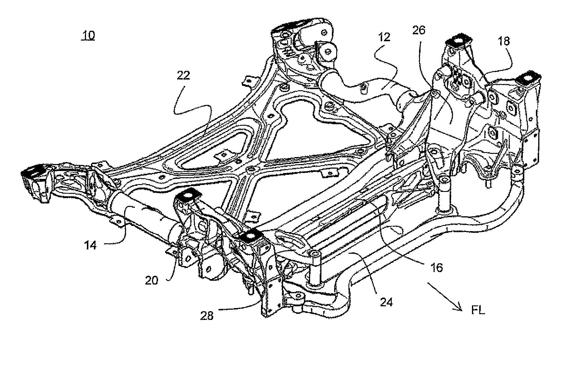
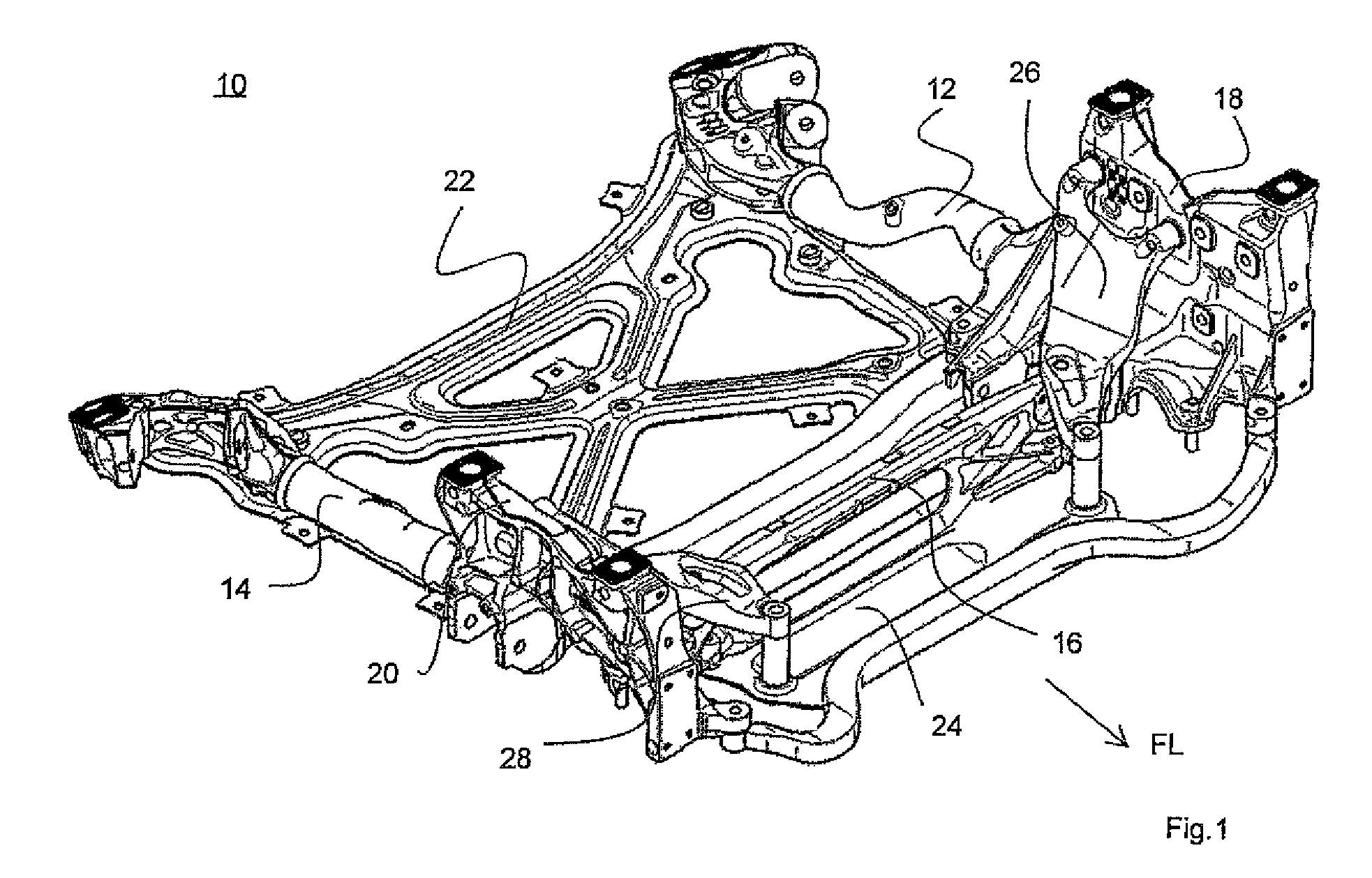
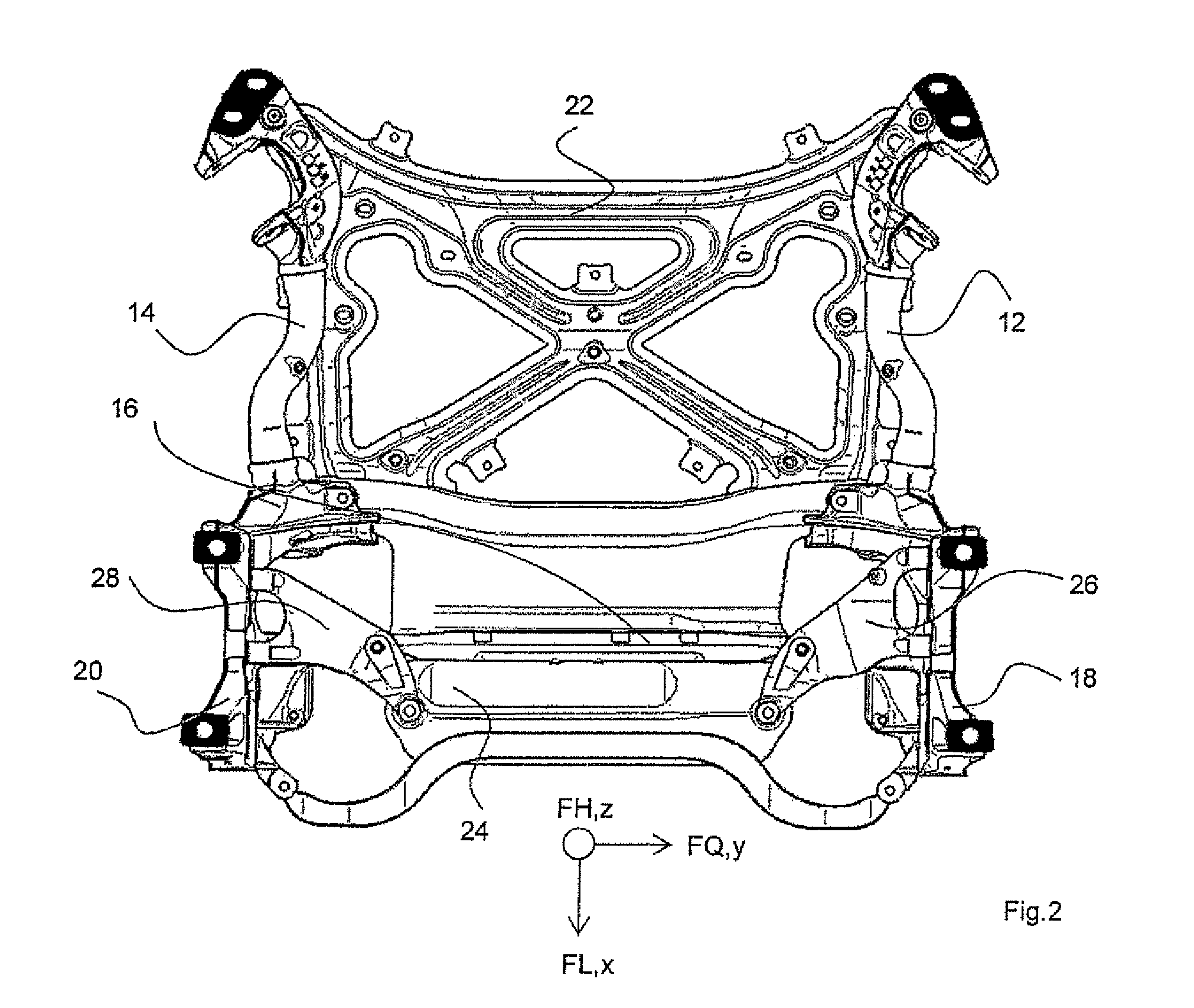
[0025]Turning now to the drawing, FIGS. 1 and 2 show a subframe for a motor vehicle overall designated with the reference numeral 10.

[0026]The subframe 10 includes substantially a first longitudinal member 12 oriented in longitudinal direction FL of the vehicle, a second longitudinal member 14 oriented in longitudinal direction FL of the vehicle and a transverse member 16 exte...


PUM


Abstract

A subframe for a motor vehicle includes at least one transverse structure oriented in a transverse direction of the vehicle, a first and a second longitudinal member oriented in a longitudinal direction of the vehicle and connected to the at least one transverse structure by respective first and second cast joints respectively arranged between the first longitudinal member and the at least one transverse structure and the second longitudinal member and the at least one transverse structure, the first and second cast joints each having bearing connection points for fastening an engine bearing. The subframe also includes connection parts, one of which is provided for each of the first and second cast joints, the connection parts each having at least one other bearing connection point for fastening the engine bearing, and multiple bearing sites via which the connection parts are fastenable on the at least one transverse structure and on the bearing connection points of the first and second cast joints.

Description

CROSS-REFERENCES TO RELATED APPLICATIONS[0001]This application claims the priority of German Patent Application, Serial No. 10 2013 016 758.2, filed Oct. 10, 2013, pursuant to 35 U.S.C. 119(a)-(d), the disclosure of which is incorporated herein by reference.BACKGROUND OF THE INVENTION[0002]The present invention relates to a subframe for a motor vehicle.[0003]The following discussion of related art is provided to assist the reader in understanding the advantages of the invention, and is not to be construed as an admission that this related art is prior art to this invention.[0004]Subframes for motor vehicles known in the art are usually formed by two spaced-apart cast joints, which are interconnected by means of a transverse member and / or a stiffening element. The subframe also includes longitudinal members, which are connected with both the cast joints and with the vehicle body. The cast joints or the longitudinal members have corresponding connection points for the arrangement of c...

Claims


Application Information

Patent Timeline
Patent Type & Authority Patents(United States)
IPC IPC(8): B62D21/11B60K5/12
CPCB62D21/11B60K5/12B60K5/1283
Inventor ISAKIEWITSCH, CHRISTIANSCHEIBLECKER, SEBASTIAN
Owner AUDI AG
Why Eureka
Try Eureka