Cutting controller

a cutting controller and controller technology, applied in the direction of manipulators, programmed manipulators, metal working devices, etc., can solve problems such as deformations in the cutting area

Inactive Publication Date: 2020-05-21
HP PELZER PIMSA OTOMOTIV ANONIM SIRKETI
View PDF0 Cites 0 Cited by
  • Summary
  • Abstract
  • Description
  • Claims
  • Application Information

AI Technical Summary

Benefits of technology

[0007]The present invention relates to a cutting controller which meets aforementio

Problems solved by technology

If the cutting is not stopped on the right tim

Method used


Image

  • Cutting controller
  • Cutting controller

Examples


Embodiment Construction

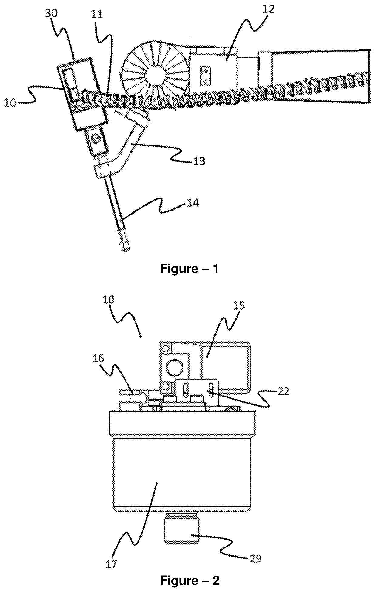
[0017]A perspective view of the assembled cutting controller (10) of the invention is given in FIG. 1. A nozzle holder (13) is attached to a robotic arm (12). The nozzle holder (13) is in connection with the nozzle (14). Thereby, the nozzle holder (13) holds the body (30). The body (30) is moved by the moving the robotic arm (12). The robotic arm (12) and the body (30) draw an outline on the material to be cut. Cutting is performed by the pressurized water from the nozzle (14), according to the outline. The nozzle (14) is connected to the pneumatic valve (17) via the nozzle connector (29). A cutting controller (10) is introduced on the pneumatic valve (17). A dual connection line (11), which is connected to the robotic arm (12), is also connected to the cutting controller (10). The dual connection line (11) comprises a structure through which electrical wiring passes, in combination with an air hose. The dual connection line (11) has a structure which is not affected by the motion o...


PUM


Abstract

A cutting controller which ensures faultless and/or correct cutting of mounting holes and/or edges of materials such as carpets by the nozzle that is connected to the robotic arm, wherein, it includes; at least one body, at least one solenoid valve which is connected to the body, at least one pneumatic valve which is connected to the body and opened by the compressed air in order to commence the cutting, at least one sensor which monitors and controls the motion of the solenoid valve and/or pneumatic valve.

Description

TECHNICAL FIELD[0001]The invention relates to a cutting controller of a waterjet, which is used for cutting mounting holes and edges of materials such as carpets.[0002]The invention particularly relates to a cutting controller which provides cutting standardization in order to verify that the desired cutting has been performed and / or to detect the quality of the performed cutting, by controlling the needle of the waterjet which constitutes a part of the robotic arm, using a suitable device.PRIOR ART[0003]In the prior art, there is an electronic valve on the robotic arm. There is a waterjet which performs cutting with pressurized water, on the robotic arm. The needle at the end of the waterjet is raised to commence the cutting. Similarly, the needle is pushed down in order to end the cutting. The desired outline is cut out with the motion of the robotic arm. When the outline is finished, cutting process is concluded by turning off the waterjet. However, opening and closing the needle...

Claims


Application Information

Patent Timeline
IPC IPC(8): B25J9/14B26D5/00B25J11/00B26F3/00
CPCB26F3/004B26D5/00B25J9/14B25J11/0055B26F2003/006
Inventor YILDIZ, RÜSTEM
Owner HP PELZER PIMSA OTOMOTIV ANONIM SIRKETI
Why Eureka
Try Eureka