Method for manufacturing a part made from a composite material by means of the injection of a laden ceramic slurry into a fibrous structure

a technology of ceramic slurry and composite material, which is applied in the direction of ceramic shaping apparatus, manufacturing tools, filtration separation, etc., can solve the problems of difficult difficult to manufacture molds and counter-molds suitable for the manufacturing of such parts, and large and thin parts such as exhaust manifolds. achieve the effect of better control of fiber volume ra

Active Publication Date: 2021-02-18
SAFRAN CERAMICS SA
View PDF0 Cites 2 Cited by
  • Summary
  • Abstract
  • Description
  • Claims
  • Application Information

AI Technical Summary

Benefits of technology

[0011]The main purpose of the present invention is therefore to overcome such disadvantages by proposing a solution for manufacturing a composite part with fibrous reinforcement allowing better control of the fiber volume rate.

Problems solved by technology

The current solutions for injection molding of ceramic matrix composite parts however encounter a problem for the manufacturing of large and thin parts such as exhaust manifolds.
For example, for parts with a diameter of 1.5 m and a thickness of 1 mm, the dimensional tolerances imposed on the mold and counter-mold are extremely fine, making it very complicated to manufacture a mold and counter-mold that are suitable for the manufacturing of such a part.
However, it is difficult to control the fiber volume rate with the solution described in WO2016 / 102842.
Moreover, the solution described in WO2016 / 102842 may also encounter problems of inhomogeneity in the deposition of the slurry powder particles inside the fibrous preform.

Method used


Image

  • Method for manufacturing a part made from a composite material by means of the injection of a laden ceramic slurry into a fibrous structure
  • Method for manufacturing a part made from a composite material by means of the injection of a laden ceramic slurry into a fibrous structure
  • Method for manufacturing a part made from a composite material by means of the injection of a laden ceramic slurry into a fibrous structure

Examples


Embodiment Construction

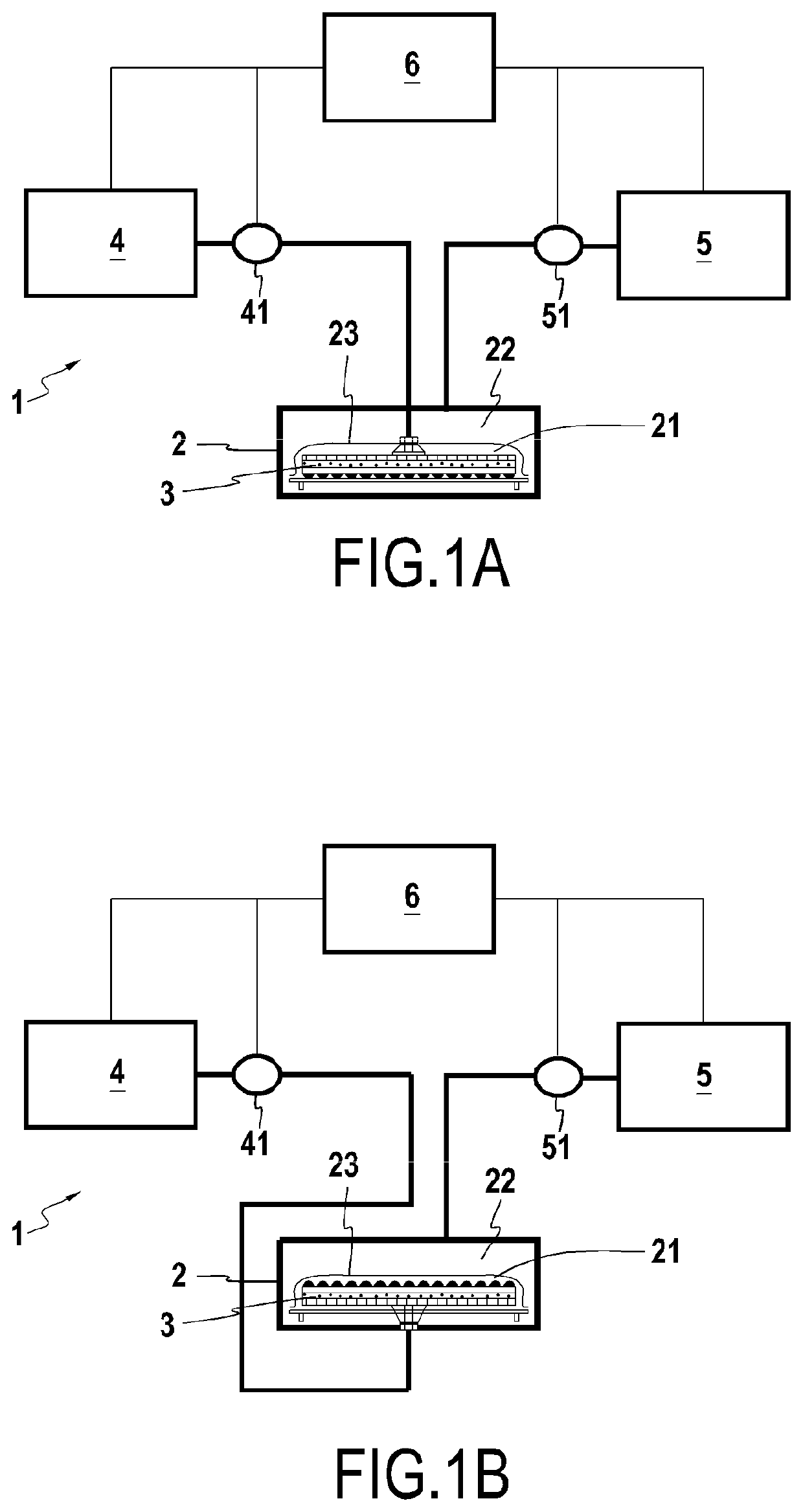
[0039]As shown in FIGS. 1a, 1b and 2, a system 1 for manufacturing a composite part comprises a mold 2 which comprises on the one hand an impregnation chamber 21 in which a fibrous preform 3 is arranged in order to be impregnated by a ceramic matrix, and on the other hand a compaction chamber 22 in which a compression fluid is injected in order to apply pressure to the preform 3 during the impregnation of said preform 3.

[0040]The impregnation chamber 21 and the compaction chamber 22 of the mold 2 are separated by a flexible membrane 23. The membrane 23 allows pressure to be applied to the preform 3 installed in the impregnation chamber 21 by injecting compression fluid into compaction chamber 22, the compression fluid applying pressure on the membrane which deforms and in turn applies pressure on the preform 3. The membrane 23 is for example made of silicone.

[0041]As shown in FIG. 1a, the slurry that is injected through the preform 3 can be injected through an inlet opening located ...


PUM

PropertyMeasurementUnit
pressureaaaaaaaaaa
pressureaaaaaaaaaa
pressureaaaaaaaaaa

Abstract

A process for manufacturing a composite part includes arranging a fibrous preform in a mold including an impregnation chamber which includes in its lower part a filter by making a first face of the preform rest on the filter, the impregnation chamber being closed by a flexible membrane placed opposite a second face of the preform, the membrane separating the impregnation chamber from a compaction chamber. The process further includes injecting a compression fluid into the compaction chamber so as to apply a first pressure on the membrane and injecting a slurry including ceramic particles into the impregnation chamber with a second pressure while maintaining the injection of the compression fluid, the second injection pressure of the slurry being lower than the first pressure on the membrane.

Description

BACKGROUND OF THE INVENTION[0001]The present invention relates to the general field of the manufacture of composite parts, in particular ceramic matrix composite (CMC) parts, i.e. comprising a fibrous reinforcement formed from fibers of ceramic material densified by a matrix also made of ceramic material, such as the oxide / oxide type, for example.[0002]Ceramic matrix composite (CMC) parts are generally manufactured by draping in a mold a plurality of fibrous layers made from ceramic material fibers, for example silicon carbide (SiC), to form a fibrous preform.[0003]The preform is then impregnated with a slurry loaded with particles of ceramic material, such as for example also SiC, by means of an[0004]“RTM” injection molding process. In the case of the manufacture of an oxide / oxide type CMC part, the fibers and the slurry particles are made of oxide, such as alumina (Al2O3).[0005]To do this, the slurry loaded with the ceramic particles is injected into the cavity separating the mold...

Claims


Application Information

Patent Timeline
Patent Type & Authority Applications(United States)
IPC IPC(8): B28B1/26B28B17/00C04B35/80C04B35/628
CPCB28B1/265B28B1/261B28B17/0081C04B2235/604C04B35/62886C04B2235/5252C04B2235/616C04B35/80C04B35/117C04B35/14C04B35/18C04B35/185C04B35/447C04B35/488C04B35/565C04B2235/5224C04B2235/5228C04B2235/5232C04B2235/5244C04B2235/5248C04B2235/5256C04B2235/5436C04B2235/5445C04B2235/6022C04B2235/6027C04B2235/77B01D29/822B29C70/443
Inventor PHILIPPE, ERICCARMINATI, PAULBOUNIA, MEDHY DAMIENDESJOYEAUX, BERTRAND
Owner SAFRAN CERAMICS SA
Why Eureka
Try Eureka