Eureka AIR delivers breakthrough ideas for toughest innovation challenges, trusted by R&D personnel around the world.

Engine pylon for coupling a jet engine to a wing of an aircraft

Active Publication Date: 2021-04-08
AIRBUS OPERATIONS SAS
View PDF0 Cites 1 Cited by
  • Summary
  • Abstract
  • Description
  • Claims
  • Application Information

AI Technical Summary

Benefits of technology

The present invention proposes the use of composite materials, such as polymer reinforced with carbon fibers, for the manufacturing of the primary box of an engine pylon. This allows for the creation of more complex and aerodynamically shaped structures, which reduces drag and improves the performance of the engine. Additionally, the use of composite components provides benefits such as improved working section, reduced mass and costs, increased interior volume, optimal aerodynamic shape, integrated structure, and reduced costs without the need for assembly of multiple components.

Problems solved by technology

As a result, simply changing the materials between a component of the primary box of the prior art and a component made from a CFRP material is not possible.
Furthermore, the use of the composite also makes it easier to produce more complex shapes of the wing type (such as double curves), which shapes may not be able to be produced with hard metal components, or may be obtained only with expensive manufacturing processes.

Method used


Image

  • Engine pylon for coupling a jet engine to a wing of an aircraft
  • Engine pylon for coupling a jet engine to a wing of an aircraft
  • Engine pylon for coupling a jet engine to a wing of an aircraft

Examples


Embodiment Construction

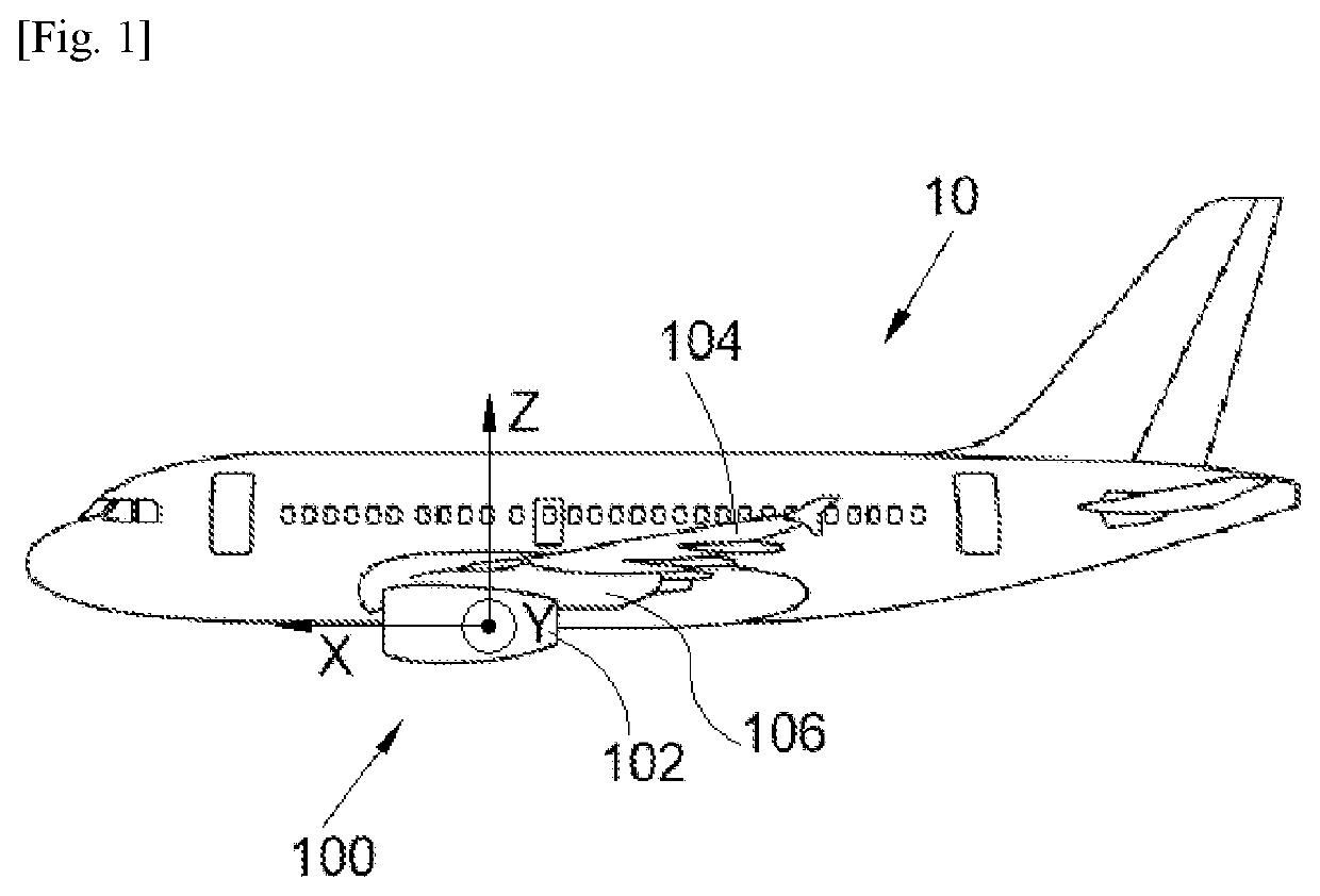
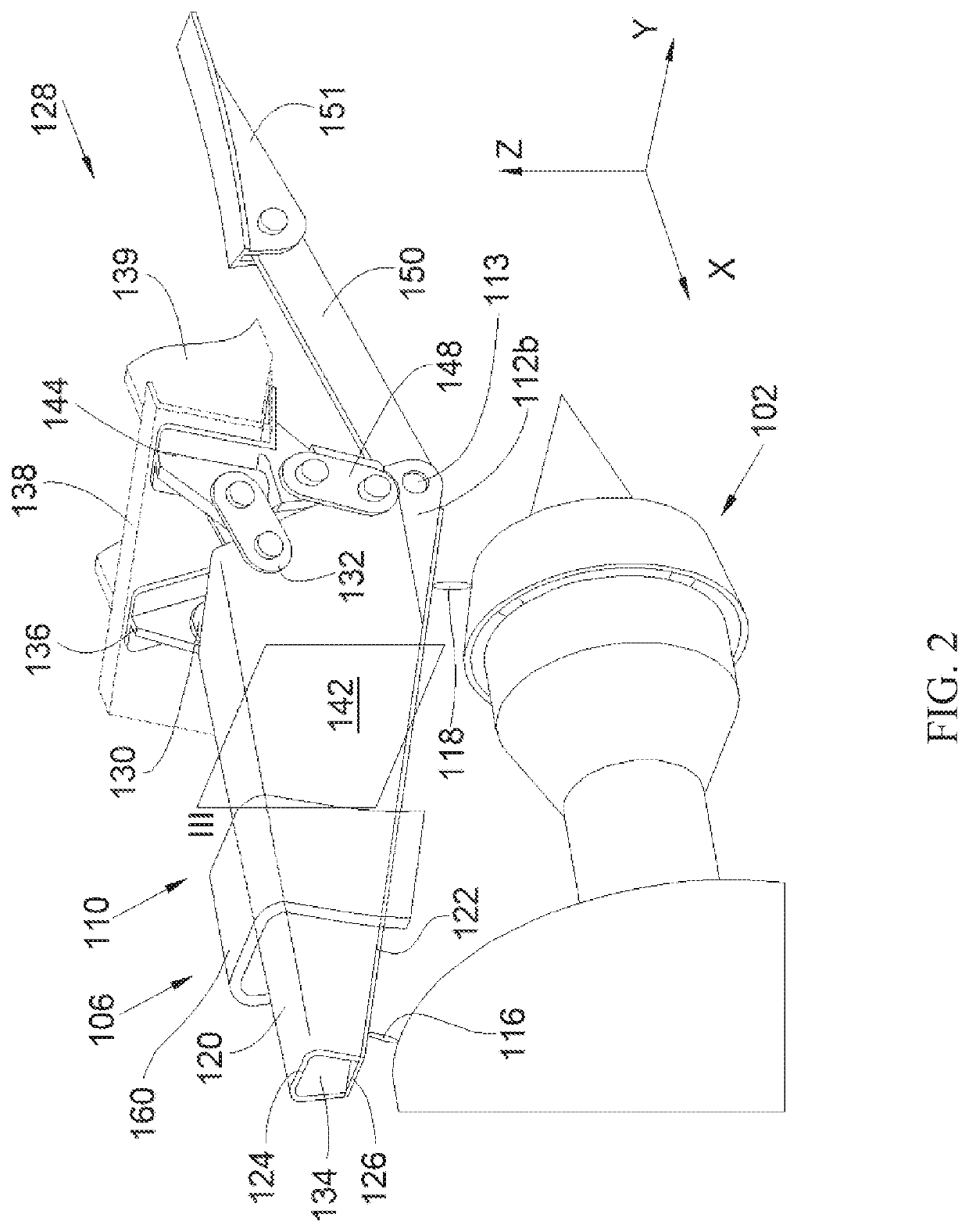
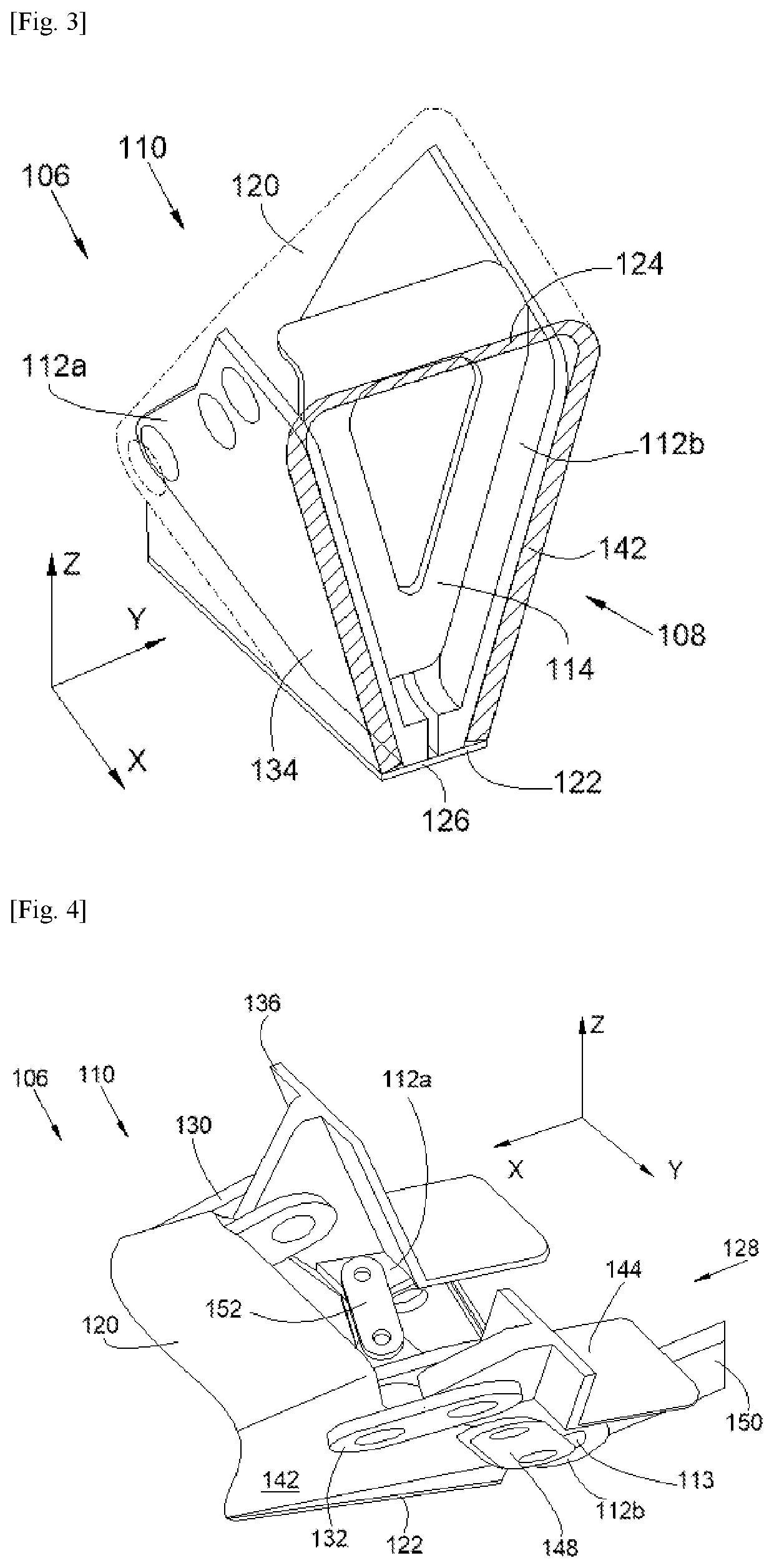
[0037]FIG. 1 shows an aircraft 10, which has a propulsion system 100 with a jet engine 102 fastened to a wing 104 of the aircraft 10 by way of an engine pylon 106 according to the invention.

[0038]In the following description, terms relating to a position are considered in relation to an aircraft in a normal flight position, i.e. as shown in FIG. 1, and the “front” and “rear” positions are considered in relation to the front and the rear of the jet engine and in relation to the direction of forward movement of the aircraft 10 when the jet engine 102 is in operation.

[0039]In the following description, and by convention, the X direction is the longitudinal direction of the jet engine, which is parallel to the longitudinal axis of said jet engine, the Y direction is the transverse direction, which is horizontal when the aircraft is on the ground, and the Z direction is the vertical direction, which is vertical when the aircraft is on the ground, these three directions X, Y and Z being m...


PUM


Abstract

An engine pylon for mounting a jet engine beneath a wing of an aircraft, the engine pylon having a primary structure having two internal lateral fittings that face one another and a rib that is fastened between the two internal lateral fittings and a primary box that at least partially surrounds the primary structure and comprises a first part made from a composite material.

Description

RELATED APPLICATIONS[0001]This application claims priority to U.S. patent application Ser. No. 62 / 880,974 filed on Jul. 31, 2019 and French Patent Application No. 1911640 filed on Oct. 17, 2019, the entireties of both of which are incorporated herein by reference.TECHNICAL FIELD[0002]The present invention relates to an engine pylon for mounting a jet engine beneath the wing of an aircraft, and to an aircraft having a jet engine, a wing, and such an engine pylon for mounting the jet engine beneath the wing.BACKGROUND[0003]Usually, for an aircraft, a propulsion assembly has a jet engine that is fastened beneath a wing of the aircraft with the aid of an engine pylon. The engine pylon is generally made up of a primary structure formed of a box made up of an upper spar, a lower spar and two lateral panels connecting the two spars, and internal ribs distributed along the box.[0004]First fastening means fasten the jet engine to the engine pylon. These fastening means conventionally compris...

Claims


Application Information

Patent Timeline
IPC IPC(8): B64D27/26B64D27/18
CPCB64D27/26B64D2027/264B64D27/18B64D29/06B64D27/402B64D27/40
Inventor BLANC, JONATHANPAUTIS, OLIVIER
Owner AIRBUS OPERATIONS SAS
Why Eureka
Eureka Blog
Learn More