
Winged chisel

a chisel and chisel blade technology, applied in the field of chisel points, can solve the problems of presenting important drawbacks, less expensive acquisition and operation of conventional in-surface soil preparation tools, and high cost of acquisition and operation, so as to reduce compaction and reduce the cost of operation. , the effect of limiting the cost of operation

Active Publication Date: 2019-03-12
KUHN KRAUSE
View PDF44 Cites 0 Cited by
  • Summary
  • Abstract
  • Description
  • Claims
  • Application Information

AI Technical Summary

Benefits of technology

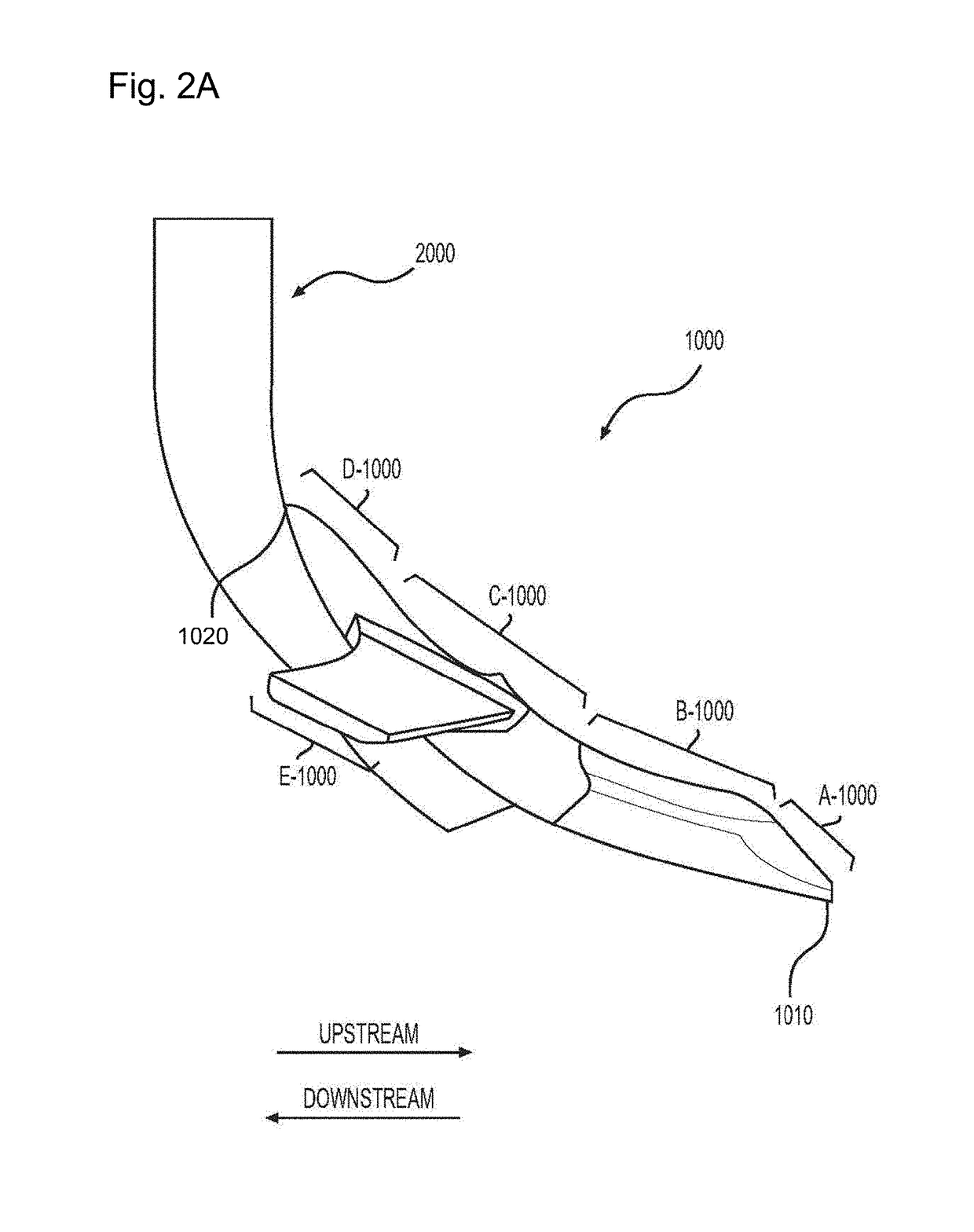
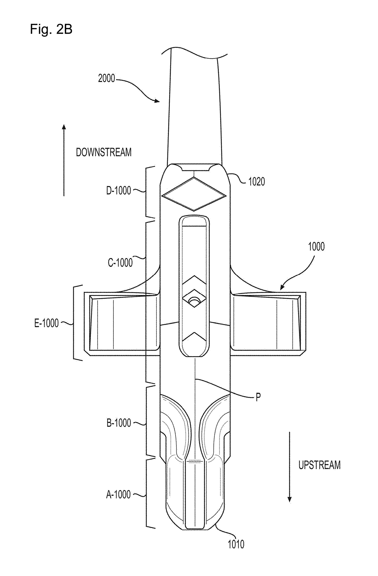
The present patent aims to reduce soil compaction while improving soil penetration by using hydrodynamic features such as raised nose, grooves, and wings on the chisel point. This helps to limit the drag generated by soil on the chisel point and reduces the cost of operation.

Problems solved by technology

Although such conventional soil preparation tools are widely used, they present important drawbacks.
On one hand, conventional in-depth soil preparation tools may be able to break the compaction layer, but may be expensive to acquire and to operate as they require high horsepower tractors to be pulled through the compaction layer.
On the other hand, conventional in-surface soil preparation tools may be less expensive to acquire and operate, but may be limited in breaking the compaction layer and providing adequate soil preparation.

Method used


Image

  • Winged chisel
  • Winged chisel
  • Winged chisel

Examples


Embodiment Construction

[0020]All publications, patent applications, patents, and other references mentioned herein are incorporated by reference in their entirety. Further, the materials, methods, and examples discussed herein are illustrative only and are not intended to be limiting.

[0021]In the drawings, like reference numerals designate identical or corresponding parts throughout the several views. Further, as used herein, the words “a”, “an”, and the like include a meaning of “one or more”, unless stated otherwise.

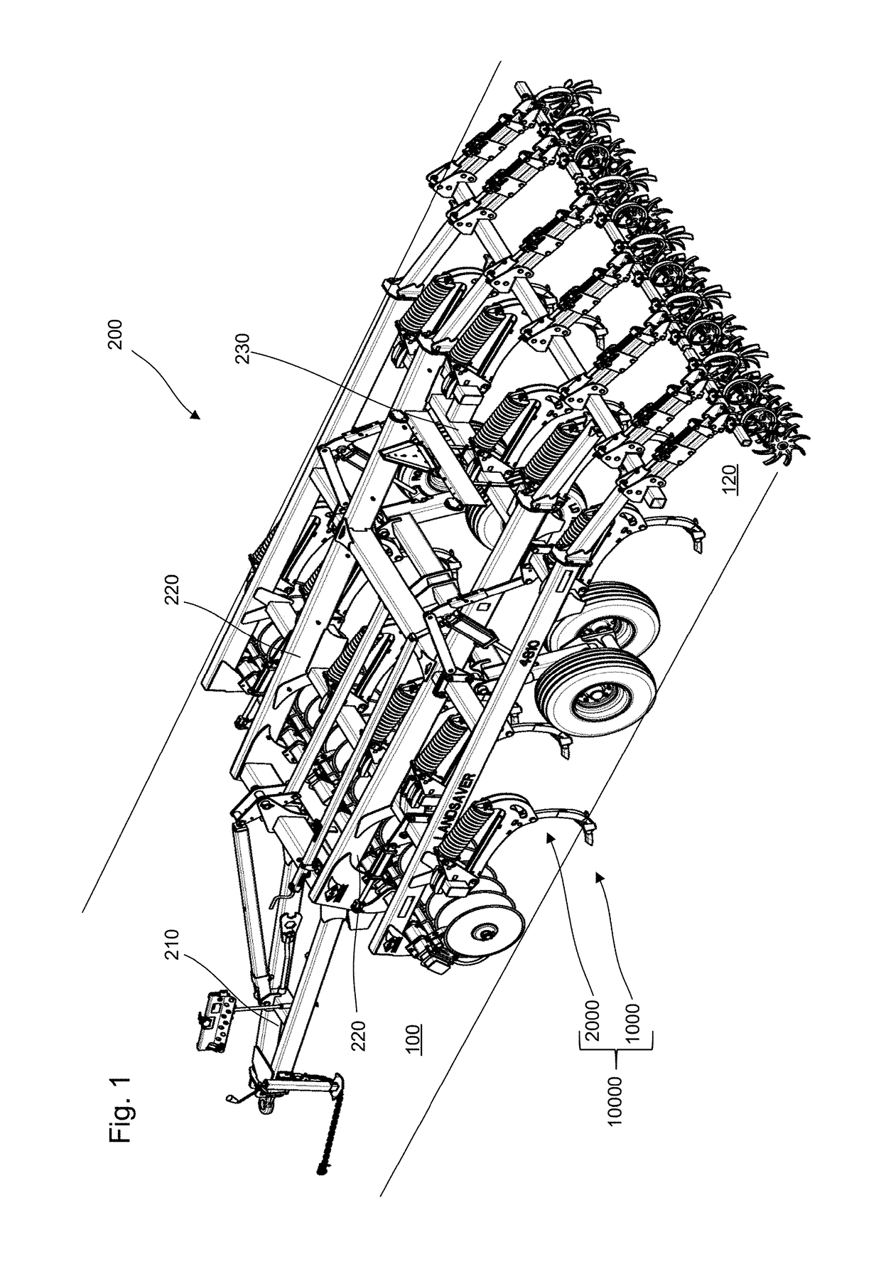
[0022]FIG. 1 is a perspective view of a plurality of chisel points 1000 mounted on an agricultural tool assembly 200, according to certain aspects of the disclosure.

[0023]The agricultural tool assembly 200 can include a front support member 210 that connects to a tractor, a back support member 230 opposite to the front support member 210, longitudinal supports members 220 extending between the front support member 210 and the back support member 230 to support a chisel assembly 10000.

[0024]T...


PUM


Abstract

A chisel point to shatter compacted soil having a nose that penetrates the soil, a tail that points in an upward direction, a head that extends in a downstream direction from the nose, a body that connects the head to the tail in the downward direction and in the upward direction, and a pair of wings that laterally protrudes from the body in the downstream direction and in a downward direction.

Description

BACKGROUNDField of the Disclosure[0001]The present disclosure relates to a ground engagement or soil tillage tool. More precisely, the present application relates to chisel points used to penetrate and break up soil.Description of the Related Art[0002]In today's agriculture, due to the use of heavy machinery, e.g., tractors, trucks, and / or agricultural tools, a compaction layer that restricts plant growth may be formed beneath the soil surface due to loads exerted on the soil by the heavy machinery.[0003]Such a demand in reducing soil compaction can be addressed by shattering and / or breaking down the compaction layer.[0004]To this end, conventional soil preparation tools that can work the soil in depth, e.g., plows, or in surface, e.g., chisel points, to shatter and / or break down the compaction layer have been employed. Although such conventional soil preparation tools are widely used, they present important drawbacks. On one hand, conventional in-depth soil preparation tools may be...

Claims


Application Information

Patent Timeline
Patent Type & Authority Patents(United States)
IPC IPC(8): A01B15/02A01B76/00
CPCA01B15/02A01B76/00A01B23/02
Inventor WEAST, DAVID H.HAGMAN, RODNEY L.
Owner KUHN KRAUSE
Learn More