Eureka AIR delivers breakthrough ideas for toughest innovation challenges, trusted by R&D personnel around the world.

Aircraft engine attachment pylon comprising a box with a circular or elliptical shaped section

Inactive Publication Date: 2011-02-17
AIRBUS OPERATIONS (SAS)
View PDF10 Cites 1 Cited by
  • Summary
  • Abstract
  • Description
  • Claims
  • Application Information

AI Technical Summary

Benefits of technology

Thus, the invention discloses a design that is radically different from that usually used for rigid attachment pylon structures, since it is rounded in shape, and more specifically it has a circular or elliptical section. This shape was selected because of the resulting compactness, and also for its very good mechanical properties due in particular to the high modulus of inertia in the three principal directions orthogonal to each other, these three principal directions corresponding to the main loading modes that are vertical bending, lateral bending and torsion. Consequently, this innovative solution advantageously offers a satisfactory compromise between the box being small enough to limit the drag generated by the secondary flow in which this box is immersed, and large enough to transmit engine forces to the aircraft fuselage.
This solution also differs from solutions according to prior art with a rectangular or square cross-section in which several accesses to the inside of the box are usually provided to install and assemble the attachment means for the components of this box. For example, these accesses may be in the form of “doors” or “openings” formed on the spars and the panels. Nevertheless, regardless of the adopted design, access for the operator is always difficult, which increases assembly and manufacturing times.
On the other hand, the adopted pylon design no longer requires any access inside the box to put said attachment means into place, since the portions to be assembled are located outside the space inside the box. Consequently, the assembly time is advantageously shortened, particular because the work to be done by the operator performing the task is made easier.
Note that the box is preferably provided without any internal ribs, even if such ribs may be provided without going outside the framework of the invention. However, forward and aft box closing ribs can be used conventionally, located on the opposite longitudinal ends of this box and therefore remaining easily accessible for the operator who will fix them.
Also preferably, the pylon comprises a hollow forward tapered and truncated segment with a circular cross-section, and a central hollow segment supporting said forward segment, the central hollow segment being approximately cylindrical in section in the form of an ellipse with an inclined axis intersecting the axis of said forward segment. This configuration facilitates the junction between the two segments. It also makes it possible to use an elliptical cross-section for the main segment and therefore to orient the major axis of the ellipse along the direction of maximum load applied to the box, which is usually in the direction of the height.

Problems solved by technology

The disadvantage of such a solution lies in the difficulty of achieving a satisfactory compromise between making the box small enough to limit the drag generated within the secondary flow in which it is immersed, and large enough to transmit engine forces to the aircraft fuselage.

Method used


Image

  • Aircraft engine attachment pylon comprising a box with a circular or elliptical shaped section
  • Aircraft engine attachment pylon comprising a box with a circular or elliptical shaped section
  • Aircraft engine attachment pylon comprising a box with a circular or elliptical shaped section

Examples


Embodiment Construction

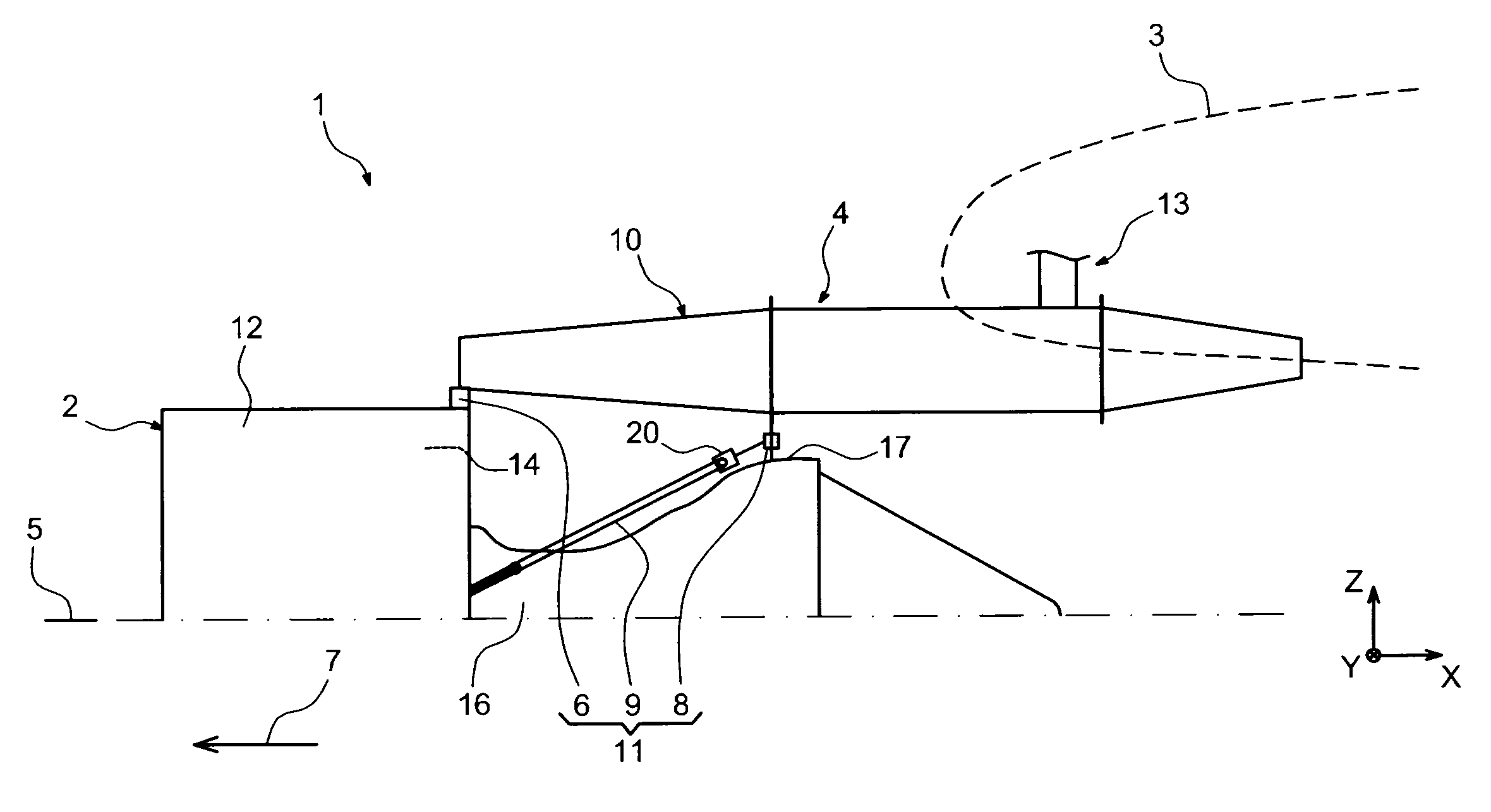
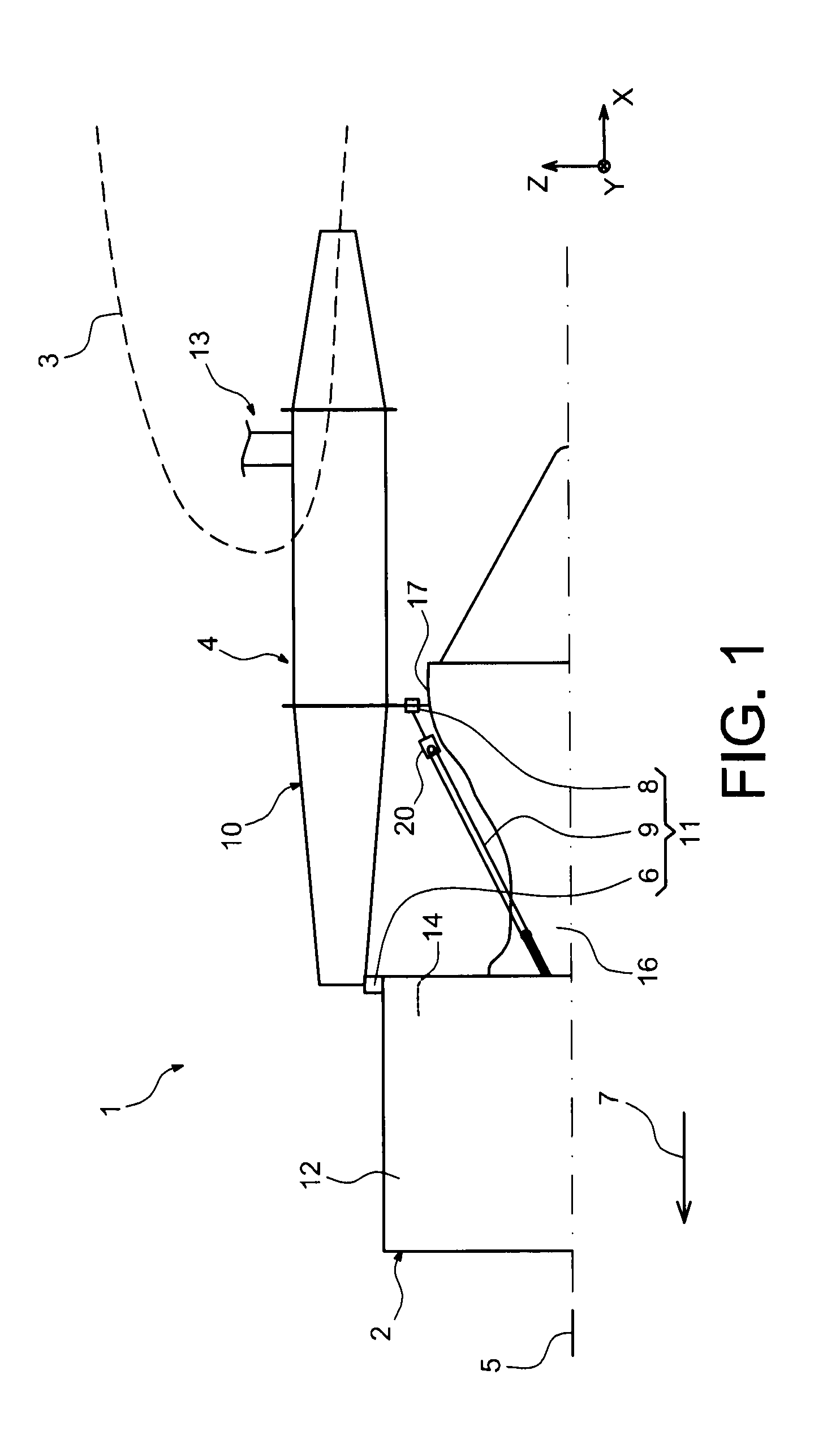
FIG. 1 shows an engine assembly 1 for an aircraft designed to be fixed under a wing 3 of this aircraft, this assembly 1 provided with an attachment pylon 4 being in the form of a preferred embodiment of this invention.

Globally, the engine assembly 1 comprises an engine such as a turbojet 2 and the attachment pylon 4, the attachment pylon in particular being provided with a rigid structure 10 and an assembly system 11 comprising a plurality of engine attachments 6, 8 and a device for resistance of thrusts 9 generated by the turbojet 2, therefore the assembly system 11 being inserted between the engine and the above-mentioned rigid structure 10 also called the primary structure. Note that the assembly 1 is intended to be surrounded by a pod (not shown) and that the attachment pylon 4 comprises another series of attachments 13 used to suspend this assembly 1 under the aircraft wing, being connected to a forward spar (not shown) of this wing.

By convention, throughout the following descr...


PUM


Abstract

An engine attachment pylon for an aircraft, including a rigid structure including a box formed by one or plural hollow segments. The section of at least one hollow segment is circular or elliptical in shape.

Description

TECHNICAL FIELDThis invention relates in general to an engine attachment pylon for an aircraft such as a turbojet. This type of attachment pylon is also called an EMS (Engine Mounting Structure), and for example can be used to suspend the turbojet below the aircraft wing, using an assembly system comprising a plurality of engine attachments.STATE OF PRIOR ARTSuch an attachment pylon is designed to form an attachment interface between an engine such as a turbojet and the aircraft wing. It transmits forces generated by its associated turbojet to the structure of this aircraft, and it also enables routing of fuel, electrical, hydraulic and air systems between the engine and the aircraft.In order to transmit forces, the pylon comprises a rigid structure, also called the primary structure, frequently of the “box” type, formed by the assembly of upper and lower spars and two lateral panels, preferably through bolt type attachment means, connecting them to transverse ribs located in an inn...

Claims


Application Information

Patent Timeline
IPC IPC(8): B64D27/26
CPCB64D27/18B64D2027/264B64D27/26B64D27/402B64D27/40
Inventor MARCHE, JACQUES HERVERAISON, FABIEN
Owner AIRBUS OPERATIONS (SAS)
Why Eureka
Eureka Blog
Learn More