Achieving convergent light rays emitted by planar array of light sources

a technology of light sources and convergent light, applied in the field of illumination of objects with convergent light rays, can solve the problems of difficult implementation, high production cost, mounting and interconnection of four separate circuit board assemblies, etc., and achieve the effect of reducing parts count, assembly time and assembly cost, and reducing assembly cos

Inactive Publication Date: 2007-01-18
ELECTRO SCI IND INC
View PDF14 Cites 40 Cited by
  • Summary
  • Abstract
  • Description
  • Claims
  • Application Information

AI Technical Summary

Benefits of technology

[0008] Thus, it would be preferable to mount the light sources (e.g., LEDs) of a darkfield ringlight on a single circuit board to reduce parts count, cost of parts, assembly time, and assembly cost. It would also be preferable to increase reliability by virtue of fewer interconnects.

Problems solved by technology

Although this arrangement provides adequate illumination, there are difficulties associated with its implementation.
For example, it is expensive to produce, mount and interconnect four separate circuit board assemblies.

Method used


Image

  • Achieving convergent light rays emitted by planar array of light sources
  • Achieving convergent light rays emitted by planar array of light sources
  • Achieving convergent light rays emitted by planar array of light sources

Examples


Embodiment Construction

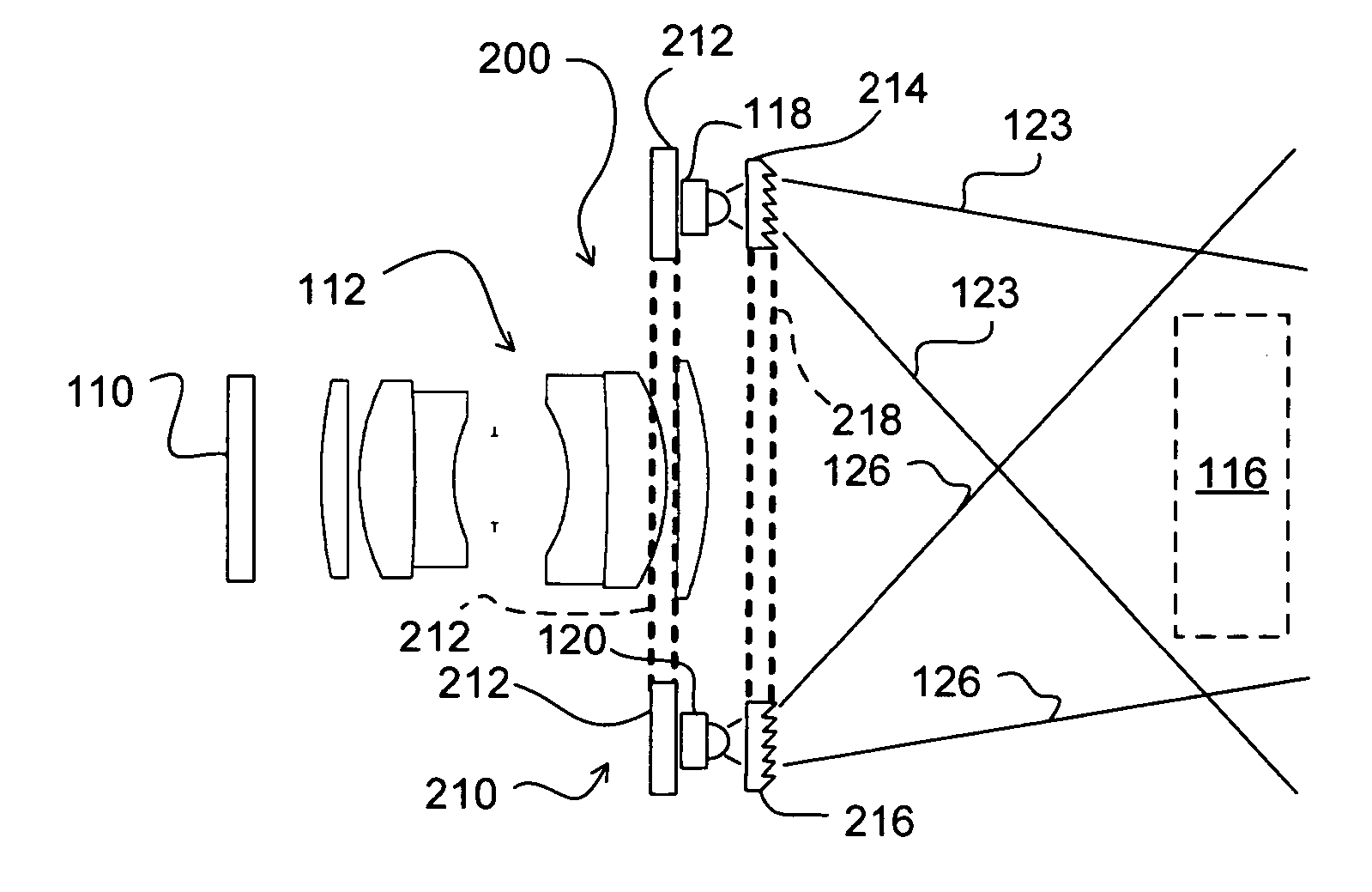
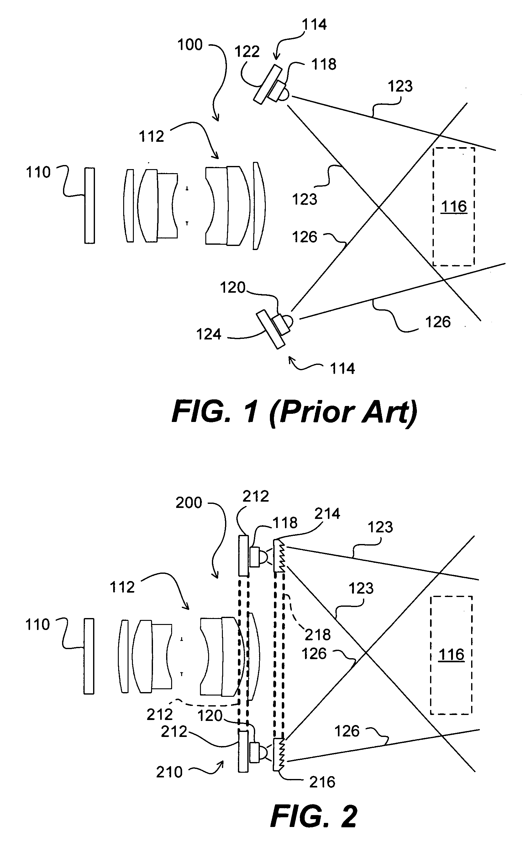
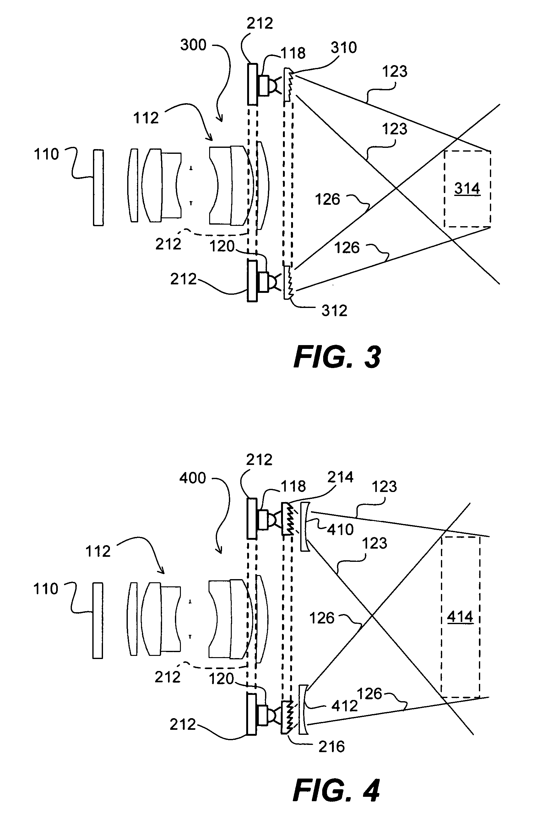
[0018] In one embodiment, light rays are emitted by a planar array of light sources and directed so as to illuminate an object under observation. Typically, although the present disclosure is not so limited, the planar array of light sources may be employed for the automated characterization and / or inspection of manufactured parts. These manufactured parts include semiconductors. Classes of semiconductors may have a nontrivial bi-directional reflectance distribution function thereby presenting varying illumination properties from Lambertian to specular. It is well understood that the time necessary to accurately inspect certain manufactured parts such as semiconductors is limited with any error reducing the efficiency of the overall production rate. An illumination device, according to one embodiment, reduces errors in inspection associated with illumination and thereby contributes to the overall efficiency of the manufacturing process.

[0019] Reference is now made to the figures in...


PUM


Abstract

Systems and methods are provided for achieving convergent light rays emitted by a planar array of light sources. In one embodiment, an imaging device is provided for inspecting semiconductors or other objects. The imaging device includes one or more imaging lens for imaging light reflected from an object. The imaging device also includes a first light source attached to a planar circuit board and a second light source attached to the planar circuit board. The imaging device further includes a first Fresnel prism for directing light from the first light source toward the object from a first direction and a second Fresnel prism for directing light from the second light source toward the object from a second direction. In one embodiment, the imaging device also includes one or more optical elements for increasing or decreasing the divergence of the light.

Description

RELATED APPLICATION [0001] This application claims the benefit under 35 U.S.C. § 119(e) of U.S. Provisional Application No. 60 / 697,651, filed Jul. 8, 2005, which is hereby incorporated by reference herein in its entirety.TECHNICAL FIELD [0002] This disclosure relates to illuminating objects with convergent light rays. BACKGROUND INFORMATION [0003] The way in which an object reflects light can vary from perfectly diffuse, known in the art as Lambertian (after Lambert), to perfectly specular (after speculum, a mirror). If an object is substantially Lambertian in nature in that the surfaces reflect light with an efficiency which is essentially independent of angle, then the illumination of such an object is relatively simple. In such a case, the uniformity of an image of an object relies only upon the uniformity and intensity of the incident illumination. An example of a Lambertian object would be paper, which can be adequately illuminated by a single point-like source of light. [0004]...

Claims


Application Information

Patent Timeline
Patent Type & Authority Applications(United States)
IPC IPC(8): G06K9/00
CPCG01N21/55G01N21/9501G01N21/8806G01B11/00
Inventor BALDWIN, LEO
Owner ELECTRO SCI IND INC
Why Eureka
Try Eureka