Optical fiber coupling module of platform-type turning and reflecting single-tube semiconductor laser
A technology of refraction reflection and fiber coupling, applied in the laser field, can solve the problems of inconsistent heat dissipation performance, low coupling efficiency, and difficult debugging, and achieve the effect of improving heat dissipation performance, prolonging the overall working life, and maintaining a high degree of stability and consistency.
- Summary
- Abstract
- Description
- Claims
- Application Information
AI Technical Summary
Problems solved by technology
Method used
Image
Examples
Embodiment 1
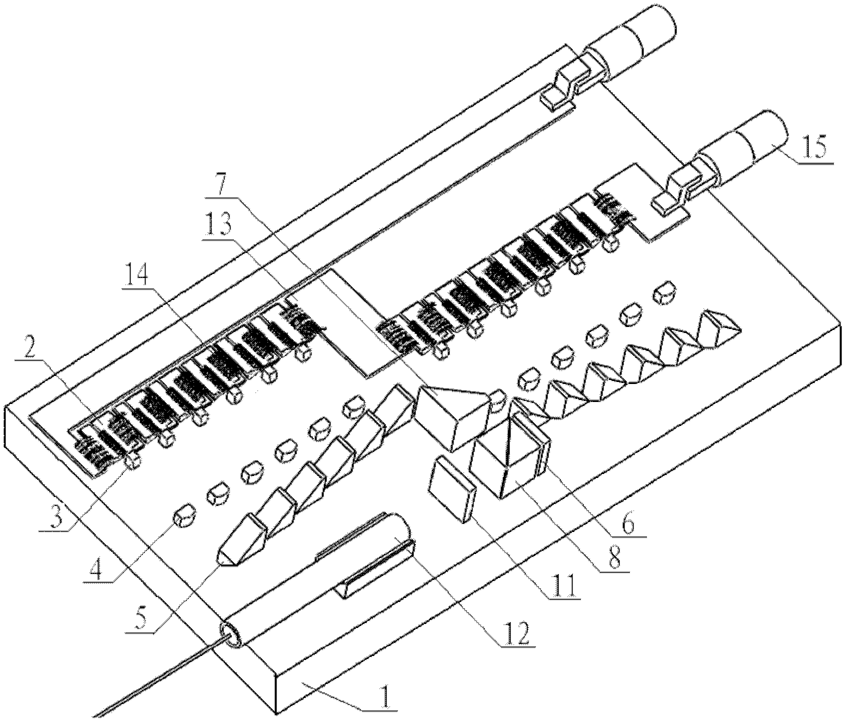
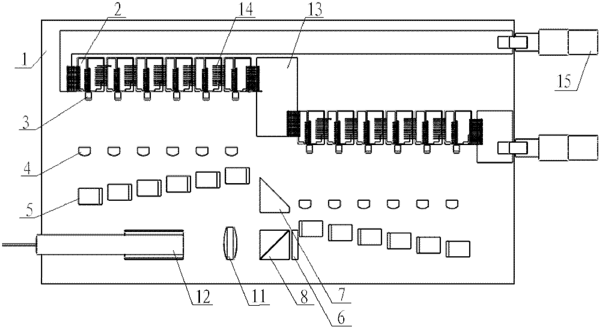
[0045] see figure 1 with figure 2 , are the stereoscopic view and the top view of the platform-type catadioptric single-tube semiconductor laser fiber coupling module in Embodiment 1, respectively. In the present embodiment, the value of m is 2, and the value of n is 6, that is, the present embodiment contains two groups of high-power semiconductor lasers, and each group is composed of 6 single-tube semiconductor lasers; in addition, a polarization beam combining prism 8 and a polarization The scheme of polarized beam combining of the glass slide 6; and the scheme of uniformly focusing the fast and slow axes of the laser beam with a convex lens 11 with a peripheral grinding is selected; in addition, in order to simplify the structure, the method of placing two sets of lasers in parallel is selected. Using a common reflective prism 7 will figure 1 The light emitted by the group of single-tube semiconductor lasers on the left in the center is reflected into the polarization b...
Embodiment 2
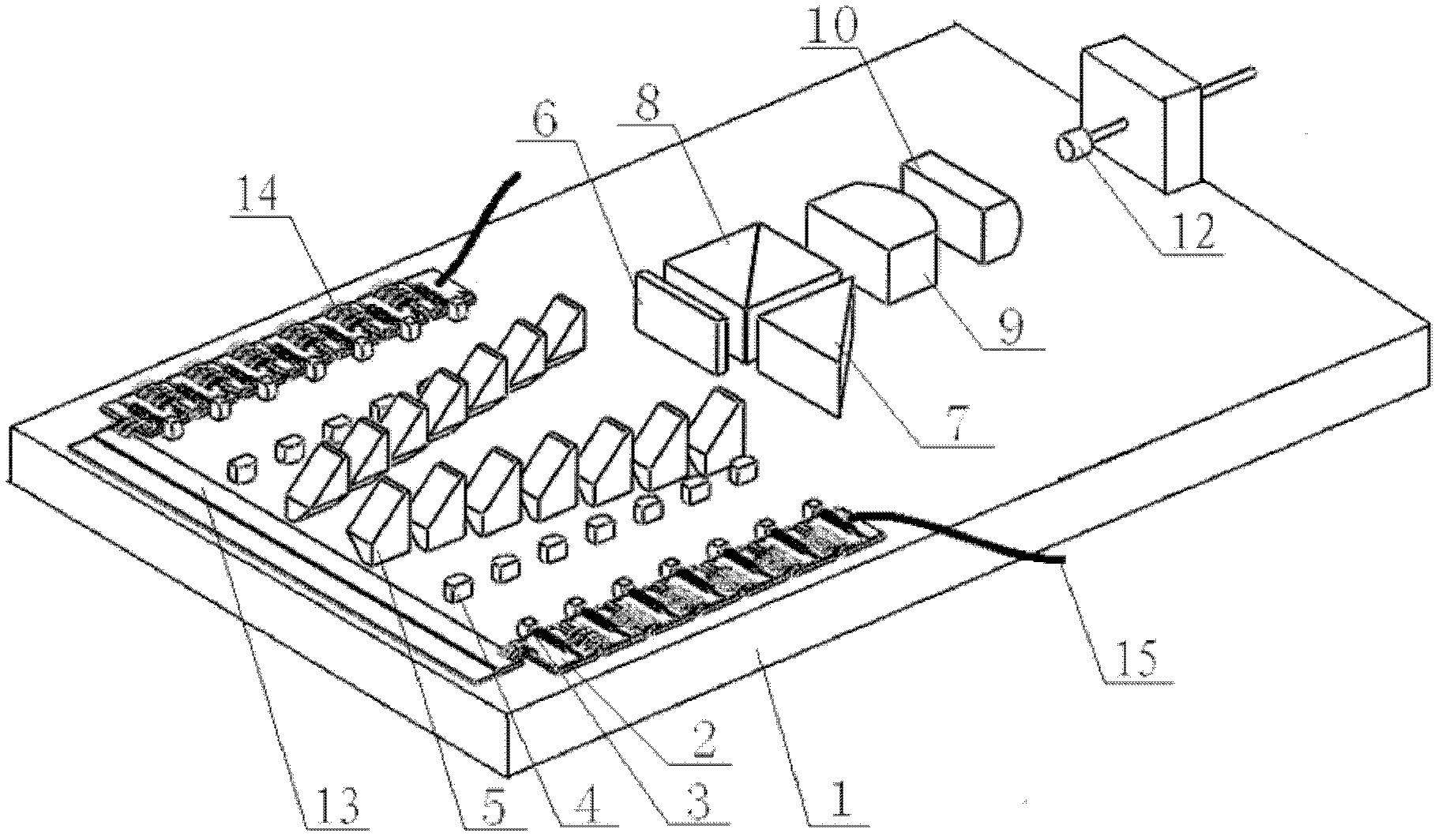
[0050] see image 3 with Figure 4 , are the stereoscopic view and the top view of the platform-type catadioptric single-tube semiconductor laser fiber coupling module in Embodiment 2, respectively. In this embodiment, the value of m, that is, the number of laser groups is 2, which is the same as in Embodiment 1, but the number n of each group containing single-tube semiconductor lasers is 7, and the arrangement of two groups of single-tube semiconductor lasers is different from that of Embodiment 1. , has become a symmetrical parallel arrangement centered on the vertical median line in the width direction of the platform; this embodiment still selects the polarization beam combining scheme containing the polarizing glass 6, the common reflective prism 7 and the polarization beam combining prism 8; And in the selection of the common reflective prism 7, a triangular reflective prism is still selected for use; but what the focusing coupling scheme of the present embodiment adop...
Embodiment 3
[0054] see Figure 5 with Image 6 , are respectively the stereoscopic view and the top view of the platform-type catadioptric single-tube semiconductor laser fiber coupling module in the third embodiment. Except for the beam focusing part of the module, this embodiment is basically the same as Embodiment 1: the m value means that the number of laser groups is 2, the number n of each group containing single-tube semiconductor lasers is 6, and the arrangement of two groups of single-tube semiconductor lasers The mode is parallel and staggered; the present embodiment still selects the polarization beam combining scheme containing polarizing glass 6, common reflecting prism 7 and polarizing beam combining prism 8; Prism; the only difference between this embodiment and Embodiment 1 is that the focus coupling scheme of this embodiment adopts the combination of fast axis focusing mirror 9 and slow axis focusing mirror 10 to realize the direction of the fast axis and the slow axis o...
PUM
 Abstract
Description
Claims
Application Information
 - R&D
- Intellectual Property
- Life Sciences
- Materials
- Tech Scout
- Unparalleled Data Quality
- Higher Quality Content
- 60% Fewer Hallucinations
Browse by: Latest US Patents, China's latest patents, Technical Efficacy Thesaurus, Application Domain, Technology Topic, Popular Technical Reports.
© 2025 PatSnap. All rights reserved.Legal|Privacy policy|Modern Slavery Act Transparency Statement|Sitemap|About US| Contact US: help@patsnap.com


