Maneuvering mechanism and closing installation or sun protection installation incorporating one such device

Active Publication Date: 2007-07-03
SIMU
View PDF13 Cites 42 Cited by
  • Summary
  • Abstract
  • Description
  • Claims
  • Application Information

AI Technical Summary

Benefits of technology

[0017]The invention also relates to an installation for closure or sun protection which comprises a maneuvering mechanism

Problems solved by technology

In these devices, there are provided, on the one hand, a tubular drive motor and, on the other hand, compensating springs, these springs and this motor having to be placed in position in the winding shaft on the site of use of the installation, while the working conditions of the installer are s

Method used


Image

  • Maneuvering mechanism and closing installation or sun protection installation incorporating one such device
  • Maneuvering mechanism and closing installation or sun protection installation incorporating one such device
  • Maneuvering mechanism and closing installation or sun protection installation incorporating one such device

Examples


Embodiment Construction

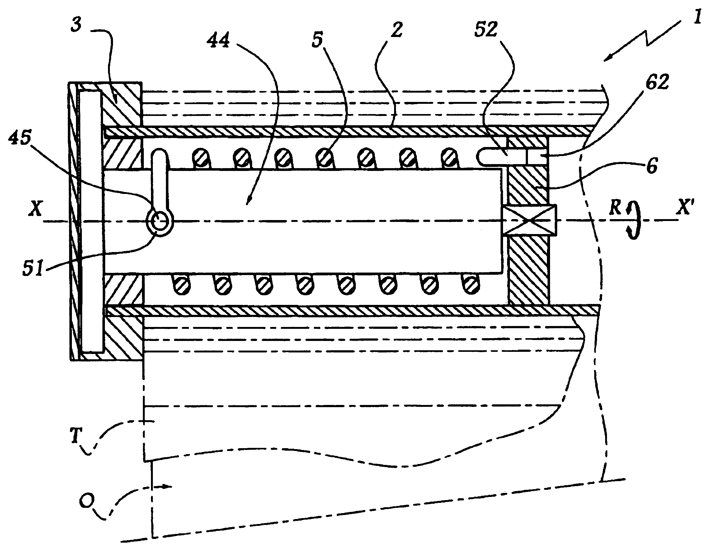
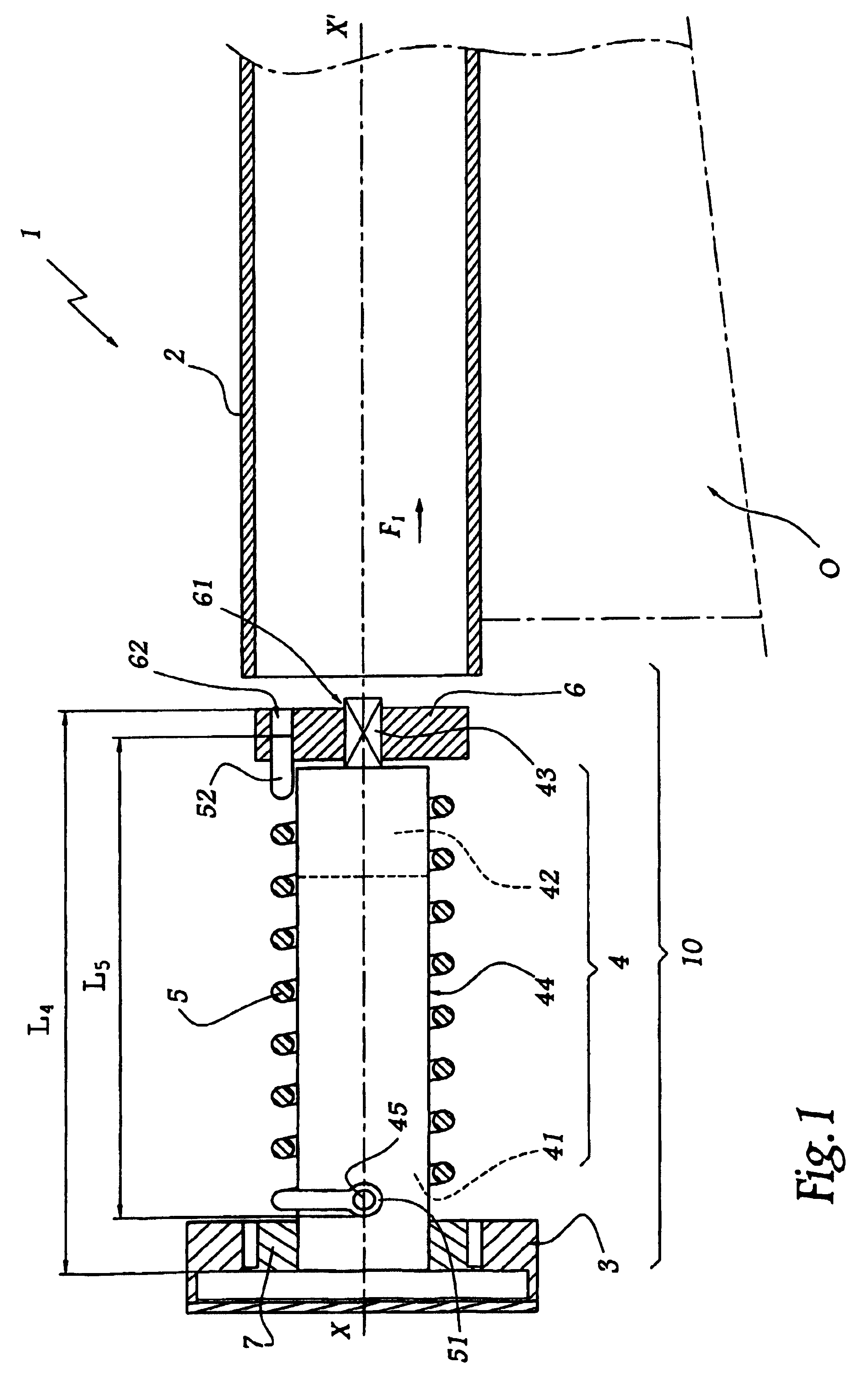
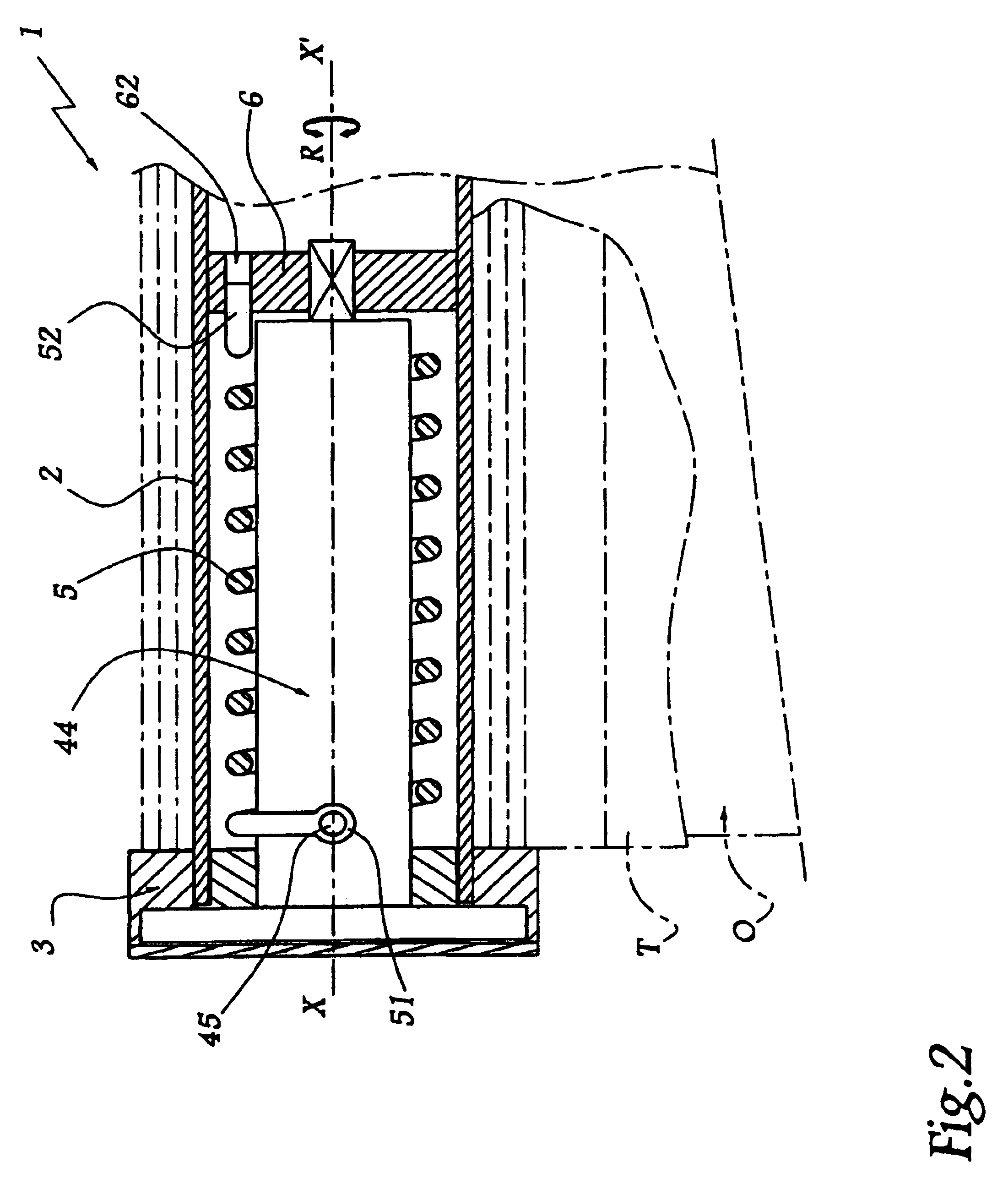
[0025]The installation shown partially in FIGS. 1 and 2 comprises a mechanism 1 making it possible to wind a screen body T more or less around a geometrical axis X-X′, this making it possible to close more or less an opening O made in the masonry of a building.

[0026]The mechanism 1 comprises a shaft 2 whose central geometrical axis merges with axis X-X′ and which is supported with respect to the structure of the building by means of a bracket 3 forming bearing.

[0027]A driving element 4 is provided to rotate the shaft about axis X-X′, as represented by arrow R in FIG. 2. This element comprises an electric motor 41 and a reduction gear 42. 43 denotes the output shaft of the element 4, and 44 its casing inside which elements 41 and 42 are housed.

[0028]A compensating spring 5 is provided in order to compensate the torque exerted by the weight of the screen body T about the axis X-X′. This spring is a torsion spring disposed helically around the casing 44 of the element 4.

[0029]The casin...


PUM


Abstract

A mechanism (1) comprising a driving element (4) for rotationally driving a winding shaft (2) for a closing or sun-protection installation of an opening (0) and at least one spring (5) for compensating a weight of the installation. The spring (5) is mounted around the driving element (4) and is jointly associated with a sub-unit (10), which can be at least partially introduced in a unitary manner inside the shaft (2). The spring (5) includes a first end (51) kinematically linked to said driving element (4) so that the first end (51) is immobilized in rotation abut an axis of rotation (X-X′) of the shaft (2), and a second end (52) kinematically linked to the shaft (2) when the sub-unit (10) is placed inside the shaft (2) so that the second end (52) rotates about the axis of rotation (X-X′).

Description

BACKGROUND OF THE INVENTION[0001]1. Field of the Invention[0002]The invention relates to a maneuvering mechanism and to a closing or sun-protection installation comprising such a mechanism.[0003]2. Brief Description of Related Art[0004]Closure installation is understood to mean doors, portals, blinds, shutters and equivalent equipment.[0005]In a closing or sun-protection installation, it is known to use a mechanical or electrical driving element for rotating, about its principal geometrical axis, a winding shaft for a closing screen of an opening, or for an effort transmission member such as a strap, associated with such a screen.[0006]It is known to compensate the torque exerted on the winding mechanism by the weight of the closing screen, such compensation being obtained by one or more so-called “compensating” springs. Winding mechanisms comprising compensating springs are known, for example, from FR-A-2 743 107, from DE-A-296 05 670 or from JP-A-2000-234485. In these devices, the...

Claims


Application Information

Patent Timeline
IPC IPC(8): A47G1/00E06B9/60E06B9/62E06B9/56E06B9/72
CPCE06B9/60E06B9/72
Inventor ARNOUX, FRANCKBRESSON, CHRISTOPHEBOUSSON, BENJAMINCHAIBA, HASSAN
Owner SIMU
Why Eureka
Try Eureka