Transformer

a transformer and transformer technology, applied in transformers/inductance cooling, basic electric elements, electrical apparatus, etc., can solve the problems of increasing the number of coils, requiring time and cost to connect each wire, etc., to improve heat dissipation, increase application, and save space

Active Publication Date: 2008-09-04
DELTA ELECTRONICS INC
View PDF22 Cites 43 Cited by
  • Summary
  • Abstract
  • Description
  • Claims
  • Application Information

AI Technical Summary

Benefits of technology

[0005]It is an object of the present invention to provide a transformer for saving space, increasing application, improving heat-dissipation and reducing assembling time and cost.

Problems solved by technology

However, under large capacity and high current requirements for the transformer 1, the number of the coils is typically increased, but it takes time and cost to connect each wire cake 20.

Method used


Image

  • Transformer
  • Transformer
  • Transformer

Examples


Embodiment Construction

[0013]The present invention will now be described more specifically with reference to the following embodiments. It is to be noted that the following descriptions of preferred embodiments of this invention are presented herein for purpose of illustration and description only. It is not intended to be exhaustive or to be limited to the precise form disclosed.

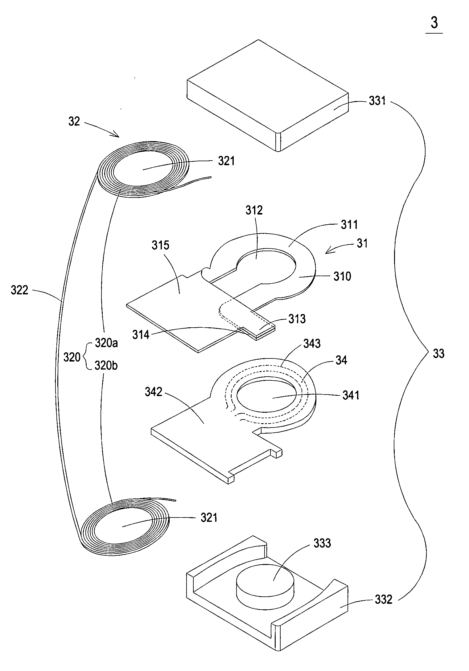
[0014]Please refer to FIG. 3, which is a schematic illustration showing a transformer according to a preferred embodiment of the present invention. As shown in FIG. 3, the transformer 3 includes a first electrical conductor 31, a second electrical conductor 32, a core set 33 and a circuit board 34, wherein the first electrical conductor 31 is used as a secondary coil of the transformer 3 and the second electrical conductor 32 is used as a primary coil of the transformer 3, but not limited thereto. The core set 33 penetrates the first electrical conductor 31, the second electrical conductor 32 and the circuit board 34, and covers ...


PUM

PropertyMeasurementUnit
conductiveaaaaaaaaaa
electricalaaaaaaaaaa
electrical conductoraaaaaaaaaa

Abstract

A transformer is provided. The transformer includes a first electrical conductor, a second electrical conductor, a circuit board and a core set. The first electrical conductor has a through hole and the second electrical conductor is electromagnetically coupled with the first electrical conductor and includes a plurality of spiral coils formed by winding a single conductive wire, each spiral coil having a through hole. The circuit board has a through hole. The core set penetrates the through hole of the first electrical conductor, the through hole of the circuit board, and the through holes of the plurality of spiral coils of the second electrical conductor, and covers at least one portion of the first electrical conductor and the second electrical conductor.

Description

FIELD OF THE INVENTION[0001]This application is a continuation-in-part of U.S. patent application Ser. No. 11 / 734,504, filed on Apr. 12, 2007, and entitled “TRANSFORMER”. The entire disclosures of the above application are all incorporated herein by reference.BACKGROUND OF THE INVENTION[0002]A transformer is an electronic assembly, which is frequently used in various electronic apparatuses for modulating different voltages in the range applicable to the power-receiving apparatuses. Referring to FIG. 1, a conventional transformer 1 includes a bobbin 11, a coil set 12, a pin seat 14 and a core 15. The coil set 12 includes a primary coil and a secondary coil each formed by winding a conductive wire around a winding region 111 of the bobbin 11. The primary coil is electromagnetically coupled with the secondary coil. The pin seat 14 is connected with the bobbin 11 and includes a plurality of pins 141, which is for electrically connecting with a circuit board 17. The core 15 is composed o...

Claims


Application Information

Patent Timeline
Patent Type & Authority Applications(United States)
IPC IPC(8): H01F27/02
CPCH01F27/22H01F27/2847H01F2027/2819H01F27/2871H01F27/306H01F27/2866
Inventor LIN, TSAI-SHENFENG, WEN-PINCHEN, YU-CHIN
Owner DELTA ELECTRONICS INC
Why Eureka
Try Eureka