Bonding device

a technology of bonding device and thread, which is applied in the direction of metal-working equipment, metal-working equipment, manufacturing tools, etc., can solve the problems of inability to efficiently reduce the dimensions of the device, time-consuming design and manufacture of the posts formed on the housing, and difficulty in producing threads in the smaller size of the post, etc., to achieve the reduction of the thickness of electronic products, the effect of reducing the assembly time of products and increasing yield

Inactive Publication Date: 2005-02-17
INVENTEC APPLIANCES CORP
View PDF9 Cites 43 Cited by
  • Summary
  • Abstract
  • Description
  • Claims
  • Application Information

AI Technical Summary

Benefits of technology

[0016] The bonding device of the invention provides several benefits.
[0017] First, volume, especially thickness, of the electronic products is reduced when applying the bonding device to the connection of the circuit unit and the predetermined element, no post need be provided on the housing, such that assembly time of the product is shortened. Yield is increased by applying Surface Mounted Technology (SMT) on the circuit unit and the predetermined connected element, and finally, without posts or the like on the housing, the design and configuration of the electronic product are variable and volume of the electronic product is further reduced.

Problems solved by technology

This causes several problems.
First, because the posts are provided on the housing of the electronic devices P1 and P2, device dimensions cannot be efficiently reduced.
As well, design and manufacture of the posts formed on the housing is time-consuming, as is assembly of the liquid crystal module, the PCB, the plates and the housing.
When the inner threaded portion is directly formed on the inner wall of the hollow post, especially for an electronic product with smaller volume, it is difficult to produce threads on the post in the smaller size.
Thus, not only are difficulties encountered in production of threads on the inner wall of the plastic post, but the threaded portion of the post has an inherently short lifetime.
The nut is then thermally pressed into the corresponding hole of the post manually, a time-consuming and costly process.

Method used


Image

  • Bonding device
  • Bonding device
  • Bonding device

Examples


second embodiment

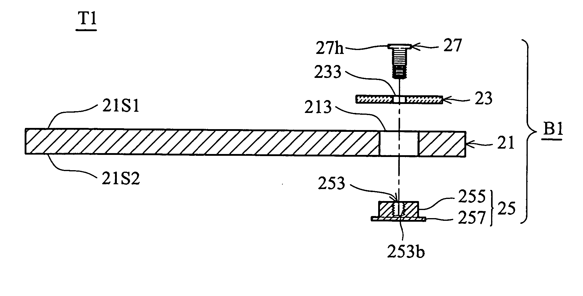
[0030] Referring also to FIG. 2b, a bonding device B1 according to the invention has several sets of bonding units, each having a base 25 and a fastening member 27. The fastening member 27 can be a bolt.

[0031] The base 25 is cylindrical, having a first connecting portion 253, a second connecting portion 255, and a stopper 257. The second connecting portion 255 is the main body of the base 25, and an outer diameter of the second connecting portion 255 is substantially equal to the inner diameter of the first positioning portions 213 of the circuit unit 21. The first connecting portion 253 is a blind hole formed in the central region of the second connecting portion 255, and a threaded area 253b is formed on the inner wall of the first connecting portion 253. The stopper 257 is a step portion formed on one end of the second connecting portion 255 and has an outer diameter exceeding that of the second connecting portion 255. Also, the outer diameter of the stopper 257 exceeds that of t...

first embodiment

[0035] The circuit unit 31 is the same as the circuit unit 21 in the first embodiment, having an upper surface 31S1, a lower surface 31S2 and a plurality of first positioning portions 313. The first positioning portions 313 are through holes penetrating the upper surface 31S1 and the lower surface 31S2. The predetermined element 33 has a plurality of second positioning portions 333. The second positioning portions 333 are through holes, each corresponding to each first positioning portion 313 of the circuit unit 31, respectively.

[0036] Referring also to FIG. 3b, a bonding device B2 according to a second embodiment of the invention has s several sets of bonding units, each having a base 35 and a fastening member 37. The fastening member 37 can be a bolt.

[0037] The base 35 is cylindrical, having a first connecting portion 353, a second connecting portion 355, a stopper 357, a sealing element 359, a front end 353E1 and a back end 353E2. The sealing element 359 is a membrane, a thin pl...


PUM

PropertyMeasurementUnit
diameteraaaaaaaaaa
structureaaaaaaaaaa
dimensionsaaaaaaaaaa

Abstract

A bonding device. A plurality of bonding units each has a base and a fastening member. Each base has a first connecting portion, a second connecting portion, and a stopper. An electronic device has a circuit unit and a predetermined element. The circuit unit has several first positioning portions and the predetermined element has several second positioning portions. The first positioning portions and the second positioning portions are through holes. When the predetermined element is attached to the upper surface of the circuit unit by aligning the second positioning portions with the corresponding first positioning portions, the second connecting portion of the base is first fit into the first positioning portions of the circuit unit, then the fastening member passes through the second positioning portion of the predetermined element to couple with the fastening member by several turns. Thus, the predetermined element is fixed on the circuit unit.

Description

BACKGROUND OF THE INVENTION [0001] 1. Field of the Invention [0002] The present invention relates to a bonding device, and in particular to a bonding device provided with a fastening member and a base to connect a printed circuit board to a tube or a liquid crystal module of an electronic device. [0003] 2. Description of the Related Art [0004] In FIG. 1a, a conventional electronic device P1 such as a mobile phone has a printed-circuit board (PCB) 11, a liquid crystal module 13, a housing 15, a plurality of bolts 17, a first plate 111 and a second plate 131. [0005] The PCB 11 is disposed on the first plate 111 and connected to the liquid crystal module 13 by a wire (not shown), and the liquid crystal module 13 is disposed on the second plate 131. A plurality of first positioning holes 113 are provided on the first plate 111, and a plurality of second positioning holes 133 corresponding to the first positioning holes 113 are provided on the first plate 111. The housing 15, provided wi...

Claims


Application Information

Patent Timeline
Patent Type & Authority Applications(United States)
IPC IPC(8): B23P19/00
CPCH01R12/7047H01R12/707Y10T29/53174Y10T29/53261Y10T29/5327Y10T29/5313
Inventor WANG, SHUN-PING
Owner INVENTEC APPLIANCES CORP
Why Eureka
Try Eureka