Eureka AIR delivers breakthrough ideas for toughest innovation challenges, trusted by R&D personnel around the world.

Turbine engine stator vane, fan casing comprising such a vane, thrust reverser system of a turbine engine equipped with such a vane and turbine engine equipped with said vane, said casing or said system

a turbine engine and stator tube technology, which is applied in the direction of machines/engines, stators, liquid fuel engines, etc., can solve the problems of increasing the length of the nacelle, increasing penalising so as to reduce the drag of the casing and the mass of the propulsion assembly, reverse the thrust necessary for the propulsion of an aircraft

Active Publication Date: 2020-06-09
SN DETUDE & DE CONSTR DE MOTEURS DAVIATION S N E C M A
View PDF9 Cites 0 Cited by
  • Summary
  • Abstract
  • Description
  • Claims
  • Application Information

AI Technical Summary

Benefits of technology

[0008]An object of various embodiments of the present invention is, in particular, to propose a new variable-orientation stator vane configuration. Another object is to provide a solution that makes it possible to reverse the thrust necessary for the propulsion of an aircraft while limiting casing drag and the mass of the propulsion assembly.
[0011]Thus, this solution enables the above-mentioned aim to be achieved. In particular, this vane firstly allows a greater freedom of movement of the vane in the turbine engine and better guidance of a flow of cold air and, secondly, it makes it possible to divert the flow of cold air circulating in the duct while limiting the drag of the nacelle and the mass. The incurved profile further improves the guidance of the flow of air by forming, for example, a ramp.

Problems solved by technology

However, this architecture has an impact on the mass of the turbine engine, in particular because of the weight of the casings enveloping each fan.
This thrust reverser system generally comprises a plurality of doors that pivot towards the exterior of the nacelle and which have the disadvantage of increasing the length of the nacelle and increasing the mass of the propulsion assembly.
The integration of this thrust reverser system into multi-fan turbine engines further penalises the mass of the propulsion assembly because the number of doors is increased and limits its integration with, for example, adjacent fans.

Method used


Image

  • Turbine engine stator vane, fan casing comprising such a vane, thrust reverser system of a turbine engine equipped with such a vane and turbine engine equipped with said vane, said casing or said system
  • Turbine engine stator vane, fan casing comprising such a vane, thrust reverser system of a turbine engine equipped with such a vane and turbine engine equipped with said vane, said casing or said system
  • Turbine engine stator vane, fan casing comprising such a vane, thrust reverser system of a turbine engine equipped with such a vane and turbine engine equipped with said vane, said casing or said system

Examples


Embodiment Construction

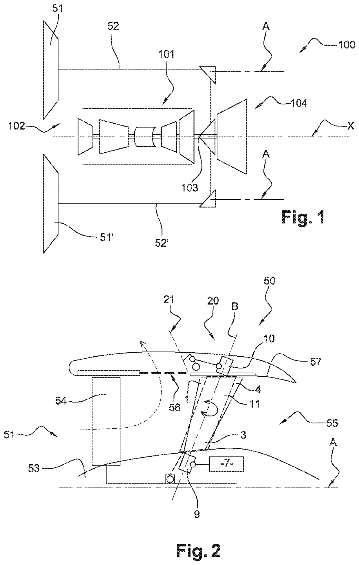
[0043]FIG. 1 shows a multi-fan turbine engine 100. Generally, this turbine engine 100 comprises a fairing 101 which has a gas generator 102 that extends substantially along an axis X. The gas generator 102 has a power transmission shaft 103 which is connected to a power transmission mechanism 104 situated downstream from the gas generator. This power transmission mechanism 104 here drives the shafts 52, 52′ of two fans 51, 51′ with offset longitudinal axes A, A′, in particular, non-coaxial with the longitudinal axis X of the gas generator 102. The fan shafts 52 each drive a fan 51. Alternatively, the power transmission mechanism can be situated upstream of the gas generator.

[0044]With reference to FIG. 2, each fan 51, 51′ is accommodated in a nacelle having a casing 50 extending along the axis A, A′ of the fan 51 and surrounding a plurality of movable fan vanes 54 which extend radially from the fan shafts 52, 52′ and are fitted in rotation relative to the casing 50. The casing 50 ha...


PUM


Abstract

A variable-orientation stator vane of a turbine engine, comprising a wall that extends between a leading edge and a trailing edge forming a chord line. The chord line increases from a root end towards a tip end of said vane. This vane is fitted pivotably in a turbine engine casing so as to divert a flow of cold air circulating in an annular duct thereof.

Description

FIELD OF THE DISCLOSURE[0001]Embodiments of the present invention relate to the field of turbine engines. They concern a turbine engine vane and in particular a stator vane, preferably with variable pitch. Embodiments of the present invention also relate to a turbine engine equipped with a fan casing equipped with such a vane or with a thrust reverser system equipped with such a vane.BACKGROUND OF THE DISCLOSURE[0002]The natural development of multiple-flow turbojet engines that have a fan, in particular upstream, is to increase propulsive efficiency via a reduction in specific thrust, which is obtained by reducing the pressure ratio of the fan, which is manifested by an increase in the bypass ratio (BPR), which is the relationship between the mass airflow through one or more than one of the ducts surrounding the gas generator by the mass airflow through the gas generator, calculated at maximum thrust when the engine is immobile in an international standard atmosphere at sea level.[...

Claims


Application Information

Patent Timeline
Patent Type & Authority Patents(United States)
IPC IPC(8): F02K1/70B64D33/04F01D17/16F04D29/54
CPCF01D17/162B64D33/04F02K1/70F04D29/542F04D29/544Y02T50/671F05D2260/50F05D2250/71F05D2220/32Y02T50/60F01D9/041
Inventor LEMARCHAND, KEVIN MORGANEMARTIN, GUILLAUME OLIVIER VARTAN
Owner SN DETUDE & DE CONSTR DE MOTEURS DAVIATION S N E C M A
Why Eureka
Eureka Blog
Learn More