Cryogenic refrigeration unit suited for delivery vehicles

a cryogenic refrigeration and vehicle technology, applied in the direction of defrosting, lighting and heating apparatus, domestic cooling apparatus, etc., can solve the problems of high maintenance cost, noisy, heavy, and high maintenance cost of typical mechanical systems, and achieve the effect of maintenance, and reducing the cost of maintenan

Inactive Publication Date: 2002-09-19
THERMO KING CORP
View PDF61 Cites 70 Cited by
  • Summary
  • Abstract
  • Description
  • Claims
  • Application Information

AI Technical Summary

Benefits of technology

0009] In preferred embodiments, engine coolant flowing through the engine, such as water or antifreeze, is directed through a heating circuit, which includes a heating coil integral with the evaporator coil. The heating coil heats the evaporating coil either to defrost the evaporator coil or to provide a relatively warm coil over which air from the blower passes, thereby providing warm air to the air-conditioned space.

Problems solved by technology

This can cause typical mechanical systems to be costly, noisy, heavy, and prone to high maintenance.
However, as with other air-conditioning systems, the cooling ability of the cryogen can produce frost on the evaporator coil.

Method used


Image

  • Cryogenic refrigeration unit suited for delivery vehicles
  • Cryogenic refrigeration unit suited for delivery vehicles
  • Cryogenic refrigeration unit suited for delivery vehicles

Examples


Embodiment Construction

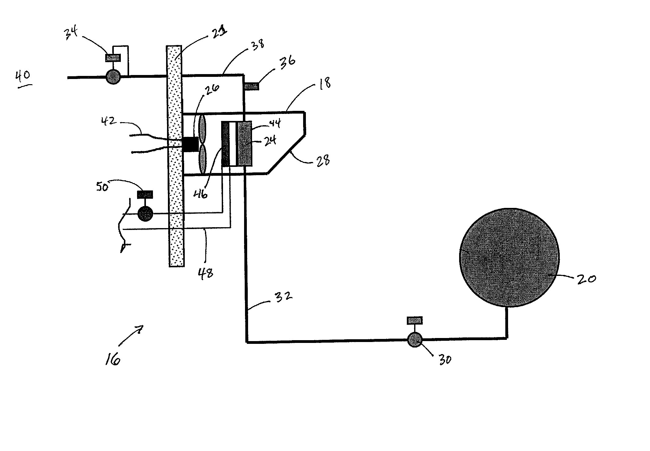
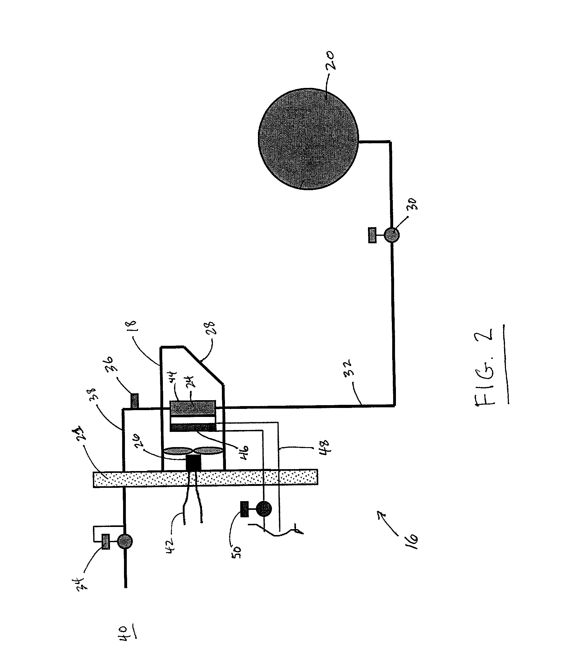
[0016] The present invention operates in conjunction with energy inherently present in a motor vehicle. For example, mechanical and electrical energy from the vehicle's engine may be utilized to fuel a heating coil and / or to drive a blower.

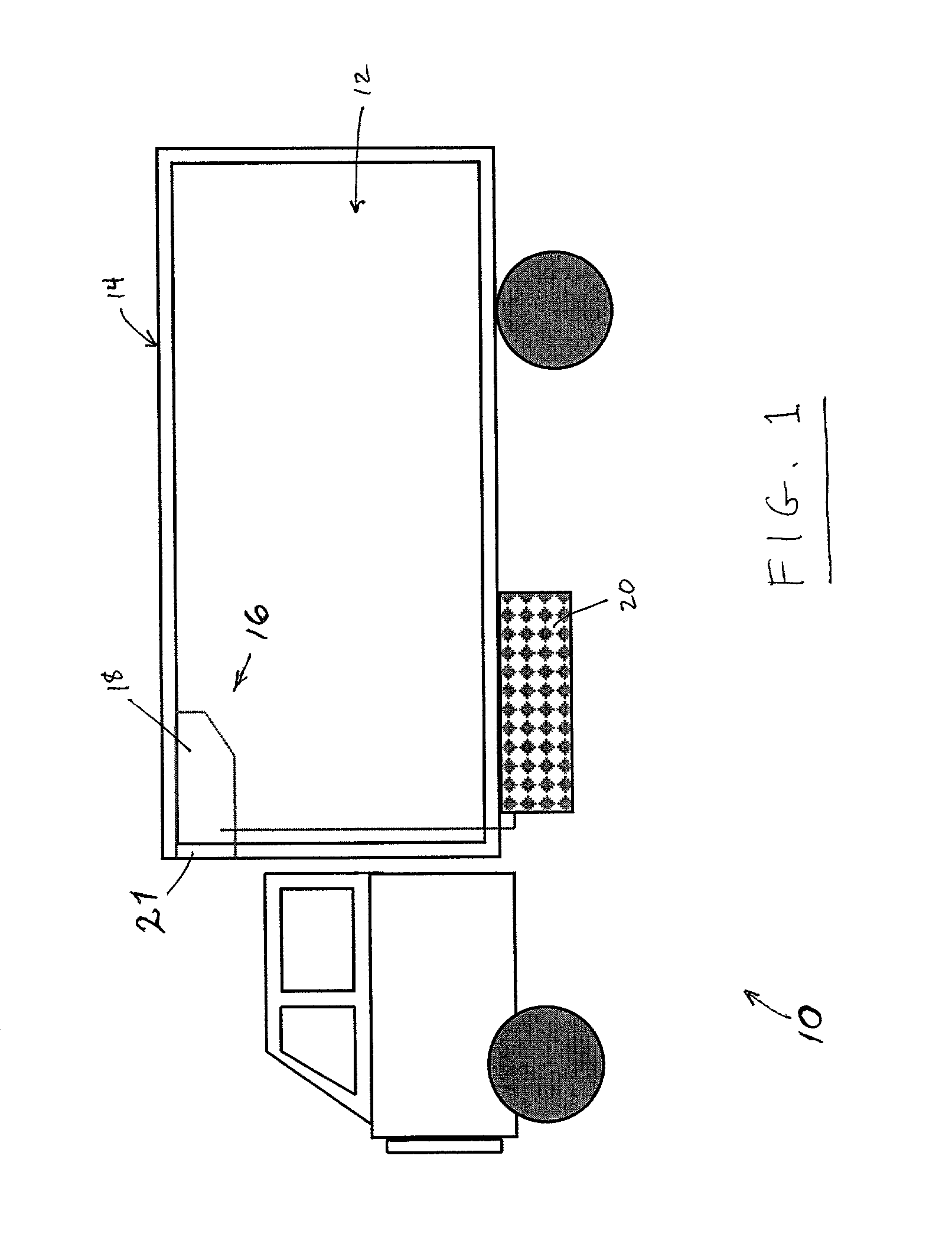
[0017] FIGS. 1 and 3 illustrate a truck 10 that includes an air-conditioned space 12 within its trailer 14. The air temperature within the air-conditioned space 12 is regulated by a temperature control system 16 that includes a temperature control housing 18 and a heat-absorbing fluid storage tank 20. The temperature control housing 18 is mounted within the air-conditioned space 12, although it may alternatively be mounted outside the air-conditioned space 12. The storage tank 20 contains a heat-absorbing fluid or cryogen, and is mounted outside of the air-condition space 12, although it may alternatively be mounted inside the air-conditioned space 12.

[0018] The temperature control housing 18 may be mounted horizontally to the ceiling of the trail...


PUM


Abstract

An apparatus to refrigerate the cargo space of delivery vehicles. It provides an environmentally friendly alternative to conventional mechanical a/c and refrigeration units. Cooling is provided by controlled evaporation of a liquefied gas such as CO.sub.2 or nitrogen. Defrost and heating requirements, if needed, are provided by hot engine coolant or by electric heaters powered from the vehicle electrical system. Airflow for the evaporator and for circulation in the temperature controlled space is provided by a blower which is mechanically or electrically driven from vehicle power. This invention can also be applied to multi-temperature control applications. The apparatus is compact and is particularly suited for small inner city delivery vehicles. FIG. 1: The sketch shows an inner city delivery truck for which this invention is most suitable. Refrigerated goods are placed in roller cages that are designed to maximize cargo hauled by use of roller cages that extend to within 2 inches of the ceiling. The evaporator section of this invention is mounted at or near the front wall of the truck and is separated from the cargo by a vertical bulkhead. The conditioned air is delivered at the bottom of the truck to avoid top freeze of perishable cargo that is in close proximity to the ceiling. FIG. 2: This shows the piping schematic and is similar to the invention described in U.S. Application Serial No. 60/238,929 (the '929 application) incorporated herein by reference. FIG. 2 shows the engine coolant coil located ahead of the CO.sub.2 coil in the direction of airflow. This prevents the coldest air from coming in contact with the engine coolant--in the cooling mode the air leaving the CO.sub.2 coil can be as low as -50.degree. F. for frozen load applications and this may cause the engine coolant to start freezing. Arrangements must be made to circulate air between the two coils in defrost mode. One means to accomplish this is to place a damper at the outlet of the evaporator section and run the fans. The damper would be closed during defrost. Another method is to place the engine coolant coil on the discharge side of the CO.sub.2 coil and use a cut-out switch if the engine coolant temperature drops below a predetermined value. In this arrangement there is no need for the damper arrangement as the heat will rise to melt any frost on the CO.sub.2 coil. If electric heat is used for defrost and heating freezing of the engine coolant is not a concern and the heaters can be fastened to the discharge side of the CO.sub.2 coil. An electric stand-by mode can be provided to power the system for cooling, heating and defrost when the vehicle is parked with the engine off. A plug-in electrical cable can provide the power needed for the controls, the fans and for heating and defrost. The figure shows the electric heaters attached on the discharge side of the CO.sub.2 coil. Operation: Detailed description is in the '929 application except for the following: The evaporator section is designed for vertical installation to maximize cargo space. Air is discharged at the bottom but may be a conventional top discharge if needed for specific applications. Conventional methods can be used to provide defrost and heating. If engine coolant is used for a heat source, it is preferable to thermally isolate the CO.sub.2 coil from the engine coolant coil to avoid freezing the coolant. The evaporator blower may be located on the inlet side of the coils rather than as shown in the figures. Unique Features: 1. Absence of a conventional condensing section on the exterior of the vehicle makes this an ideal refrigeration unit for small inner city delivery vehicles. Many of the truck cabs are now almost full height (same as the truck body) and there is limited space for the condensing section. 2. Cold plates can be used and still maximize cargo cube. However, this invention has 30-40% less weight than comparable "cold plate" systems. 3. Other features are described in the '929 application.]

Description

CROSS-REFERENCE TO RELATED APPLICATIONS[0001] This application claims priority under 35 U.S.C. .sctn. 119 to U.S. Provisional Patent Application No. 60 / 238,929 titled TEMPERATURE CONTROL SYSTEM, and filed on Oct. 10, 2000.BACKGROUND AND SUMMARY OF THE INVENTION[0002] The present invention relates to temperature control systems, and particularly to cryogenic temperature control systems. More particularly, the present invention relates to cryogenic temperature control systems which include a heating coil and blower.[0003] Conventional temperature control systems typically include mechanical, non-mechanical, and hybrid systems. These systems are applicable to both stationary and mobile applications. In motor vehicles, these systems are particularly applicable to, for example, trucks having air-conditioned trailers or containers, buses having air-conditioned passenger cabins, etc. Mechanical systems compress and condense a refrigerant and subsequently expand it before passing the refrig...

Claims


Application Information

Patent Timeline
Patent Type & Authority Applications(United States)
IPC IPC(8): B60H1/00B60H1/32B60P3/20F25D3/10F25D21/08F25D21/12F25D29/00
CPCB60H1/00014B60H1/32B60H1/3202B60P3/20F25D3/105F25D21/08F25D21/12F25D29/001F25D29/003Y02T10/88B60H1/3232
Inventor VIEGAS, HERMAN H.SESHADRI, JAYARAMNILSSON, HANS-OLOF
Owner THERMO KING CORP
Why Eureka
Try Eureka