Refrigerator

a technology for refrigerators and freezers, applied in the field of refrigerators, can solve the problems of increasing manufacturing costs and power consumption of refrigerators, increasing manufacturing costs, and complicated manufacturing processes, and achieving the effect of simplifying the structure of feeding water and minimizing the loss of cold air in storage spa

Active Publication Date: 2006-10-05
LG ELECTRONICS INC
View PDF9 Cites 70 Cited by
  • Summary
  • Abstract
  • Description
  • Claims
  • Application Information

AI Technical Summary

Benefits of technology

[0013] Another object of the present invention is to provide a refrigerator wherein the loss of cold air from a storage space can be minimized when the storage space is opened and closed.
[0014] A further object of the present invention is to provide a refrigerator including an icemaker and dispenser wherein a structure for feeding water can be simplified.

Problems solved by technology

However, the aforementioned related art refrigerator has the following problems.
Therefore, since the total length of supply tubes 110′, 106′, 108′ and 112′ are increased, there is a problem in that the manufacturing cost thereof are increased and the manufacturing process is also complicated.
Further, since the icemaker 106 is provided in the refrigerating chamber, there is also another problem in that the supply tube 106′ may be frozen at an interval where it penetrates through the freezing chamber.
However, the manufacturing cost and power consumption of the refrigerator are increased due to the use of an additional heater.
In some design conditions, however, there is a limitation on the installation of the icemaker 106 depending on where the freezing chamber should be disposed.
For example, if the dispenser is installed on a front surface of the door of the freezing chamber in a case where the freezing chamber is formed at a relatively lower portion of the refrigerator body, it is very inconvenient of a general user to take the ice from the dispenser.
On the other hand, if the icemaker is installed in the freezing chamber in a case where the freezing chamber is formed at the lower portion of the refrigerator body and the refrigerating chamber is formed at an upper portion of the refrigerator body as mentioned above, there is a further problem in that it is difficult to control the temperature of the refrigerating chamber or the ice-making capability of the icemaker is lowered.
In addition, in a case where a single door 102 or 104 is used to open and close the freezing or refrigerating chamber of the refrigerator body 100, there is a further problem in that the loss of cold air from the chamber is increased.
In particular, since the size of the refrigerator has been recently tending to increase, the loss of cold air becomes relatively larger.

Method used


Image

  • Refrigerator
  • Refrigerator
  • Refrigerator

Examples


Embodiment Construction

[0054] Hereinafter, preferred embodiments of a refrigerator according to the present invention will be described in detail with reference to the accompanying drawings.

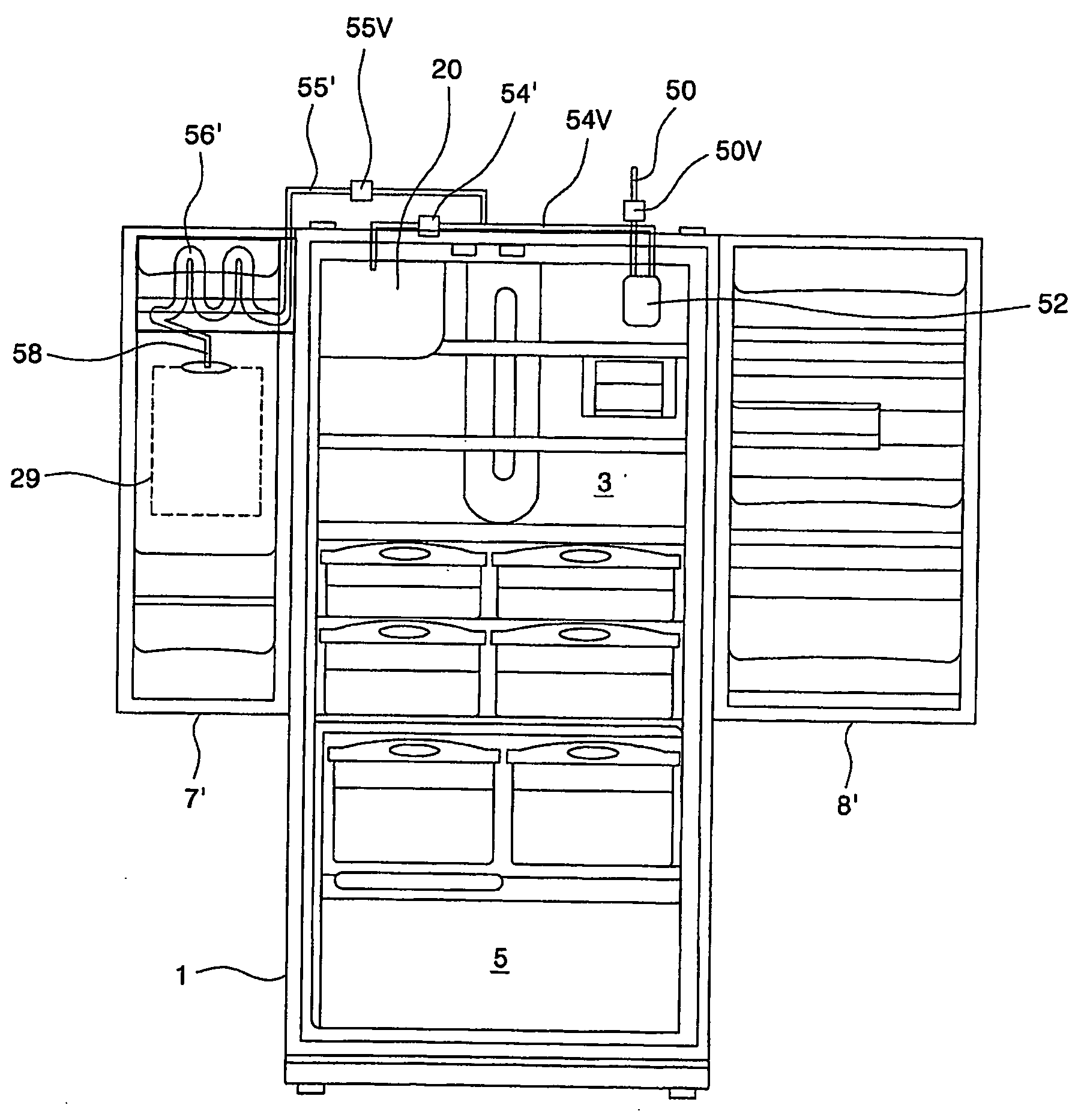
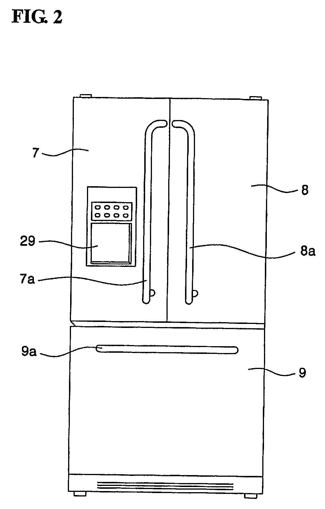
[0055]FIG. 2 shows a front view of an external appearance of a first embodiment of a refrigerator according to the present invention, and FIG. 3 shows a sectional view of the internal configuration of the first embodiment of the refrigerator according to the present invention.

[0056] Referring to these figures, a storage space such as a refrigerating chamber 3 and a freezing chamber 5 is formed in a refrigerator body 1. The refrigerating chamber 3 is formed at a relatively upper portion of the refrigerator body 1, while the freezing chamber 5 is formed at a relatively lower portion of the refrigerator body 1. The refrigerator body 1 is vertically partitioned into the refrigerating and freezing chambers 3 and 5 by means of a barrier 4.

[0057] The refrigerating and freezing chambers 3 and 5 are formed to be open toward ...


PUM

PropertyMeasurementUnit
temperaturesaaaaaaaaaa
widthsaaaaaaaaaa
widthaaaaaaaaaa

Abstract

In the related art refrigerator, its structure for supplying water to a dispenser and water tank was complicated. In addition, since an icemaker is installed in a refrigerating chamber of the refrigerator, there is a problem in that the water supplied into the icemaker is frozen. Furthermore, if the icemaker is installed in the freezing chamber of the refrigerator in which the refrigerating chamber is formed at a lower portion thereof and a refrigerating chamber is formed at an upper portion thereof, there is another problem in that it is difficult to control the temperature in the refrigerating chamber or ice-making capability of the icemaker is lowered. The present invention is directed to a refrigerator. According to an aspect of the present invention for solving the above problems, there is provided a refrigerator including a refrigerating chamber formed at a relatively upper portion of a refrigerator body and a freezing chamber formed at a relatively lower portion of the refrigerator body, which comprises an ice-making chamber which is partitioned in the refrigerating chamber by means of insulating walls and includes an icemaker for making ice and an ice storage for storing the ice made in the icemaker, a first heat exchanger for generating cold air to regulate the temperature in the ice-making chamber, and a second heat exchanger for generating cold air to regulate the temperature in the freezing and refrigerating chambers, wherein the first and second heat exchanger are components of a heat exchange cycle. According to the refrigerator of the present invention so configured, there are advantages in that the temperature in the refrigerating chamber can be accurately controlled, the loss of cold air can be minimized and the structures for supplying water into the icemaker and the dispenser can be simplified.

Description

TECHNICAL FIELD [0001] The present invention relates to a refrigerator, and more particularly, to a refrigerator wherein a refrigerating chamber is provided at a relatively upper portion thereof, a freezing chamber is provided at a relatively lower portion thereof, and a structure for making ice is also provided in the refrigerating chamber. BACKGROUND ART [0002]FIG. 1 shows the configuration of a side-by-side refrigerator in which a refrigerating chamber and a freezing chamber are provided to stand together side by side. Referring to this figure, a refrigerator body 100 includes the freezing and refrigerating chambers which are open toward a front direction and stand together side by side. The refrigerating and freezing chambers are opened and closed by a door 102 of the freezing chamber and a door 104 of the refrigerating chamber, respectively. The doors 102 and 104 are pivotally supported by hinges 102′ and 104′ provided at upper and lower ends of both lateral sides of the refrig...

Claims


Application Information

Patent Timeline
Patent Type & Authority Applications(United States)
IPC IPC(8): F25C5/18F25D11/02B67D1/08B67D7/80F25D23/02F25D23/12
CPCB67D1/0858Y10T29/53F25C1/24F25C5/005F25C5/185F25C2400/10F25C2400/14F25C2500/02F25D11/022F25D23/02F25D23/126F25D2323/021F25D2400/06Y10S277/921F25C1/04F25C5/22Y10T137/0318F25D25/025F25D11/02
Inventor KIM, IL-SHINYU, SEON-ILSEOK, KUN-JUNKWON, YONG-CHOL
Owner LG ELECTRONICS INC
Why Eureka
Try Eureka