Backlight module and display device

a backlight module and display device technology, applied in the field of display panels, can solve the problem of increasing the width of the frame of the display device adjacent to the light sour

Inactive Publication Date: 2021-11-04
WUHAN CHINA STAR OPTOELECTRONICS TECH CO LTD
View PDF0 Cites 2 Cited by
  • Summary
  • Abstract
  • Description
  • Claims
  • Application Information

AI Technical Summary

Problems solved by technology

In current technology, light sources of display devices are fixed on inner sides of brackets near light guiding plates, so that a sufficient space is reserved between the brackets and the light guiding plates to place the light sources, resulting in a large distance between the brackets and the light guiding plates, thereby causing an increase in width of frames of the display devices adjacent to the light sources.

Method used


Image

  • Backlight module and display device
  • Backlight module and display device
  • Backlight module and display device

Examples


Embodiment Construction

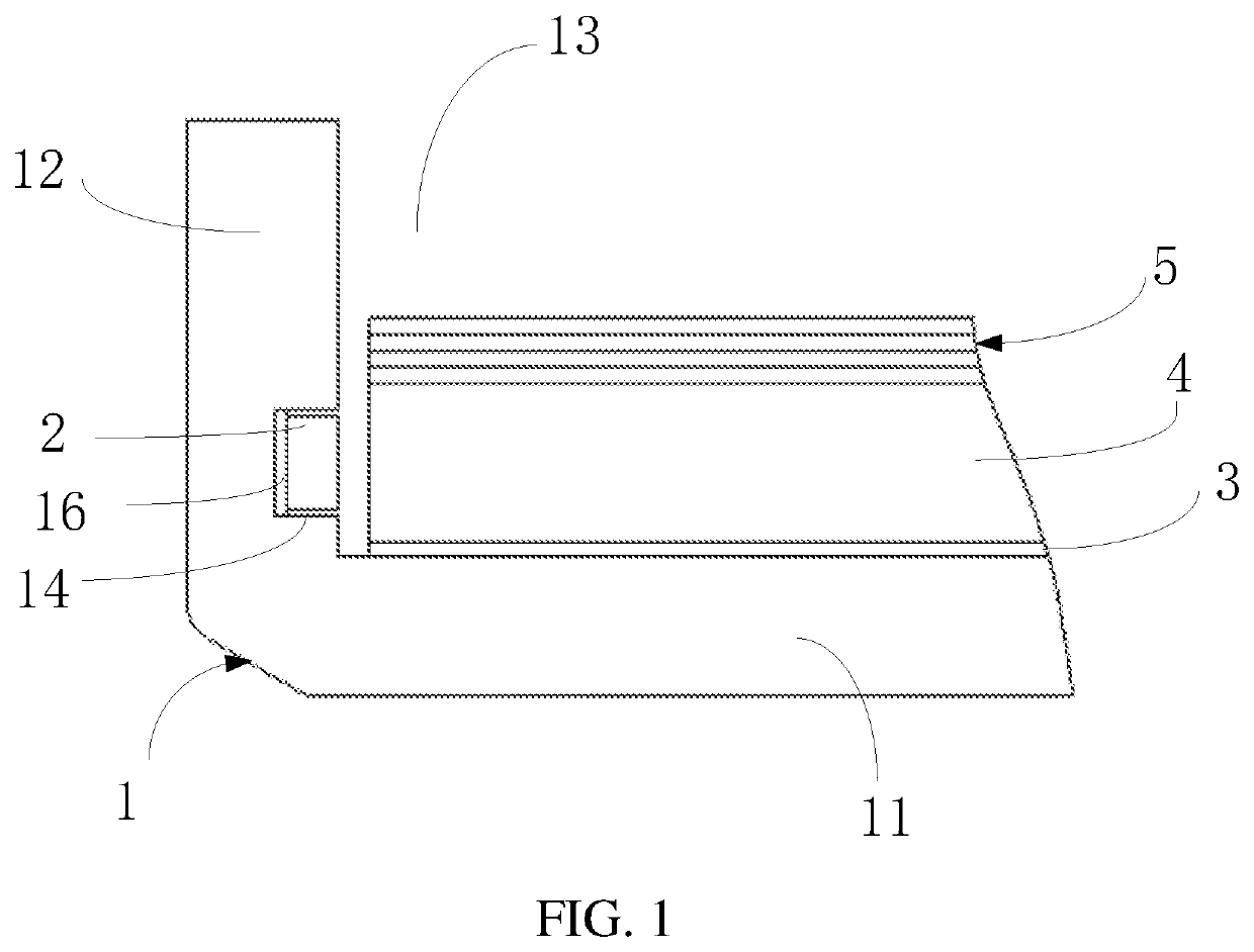
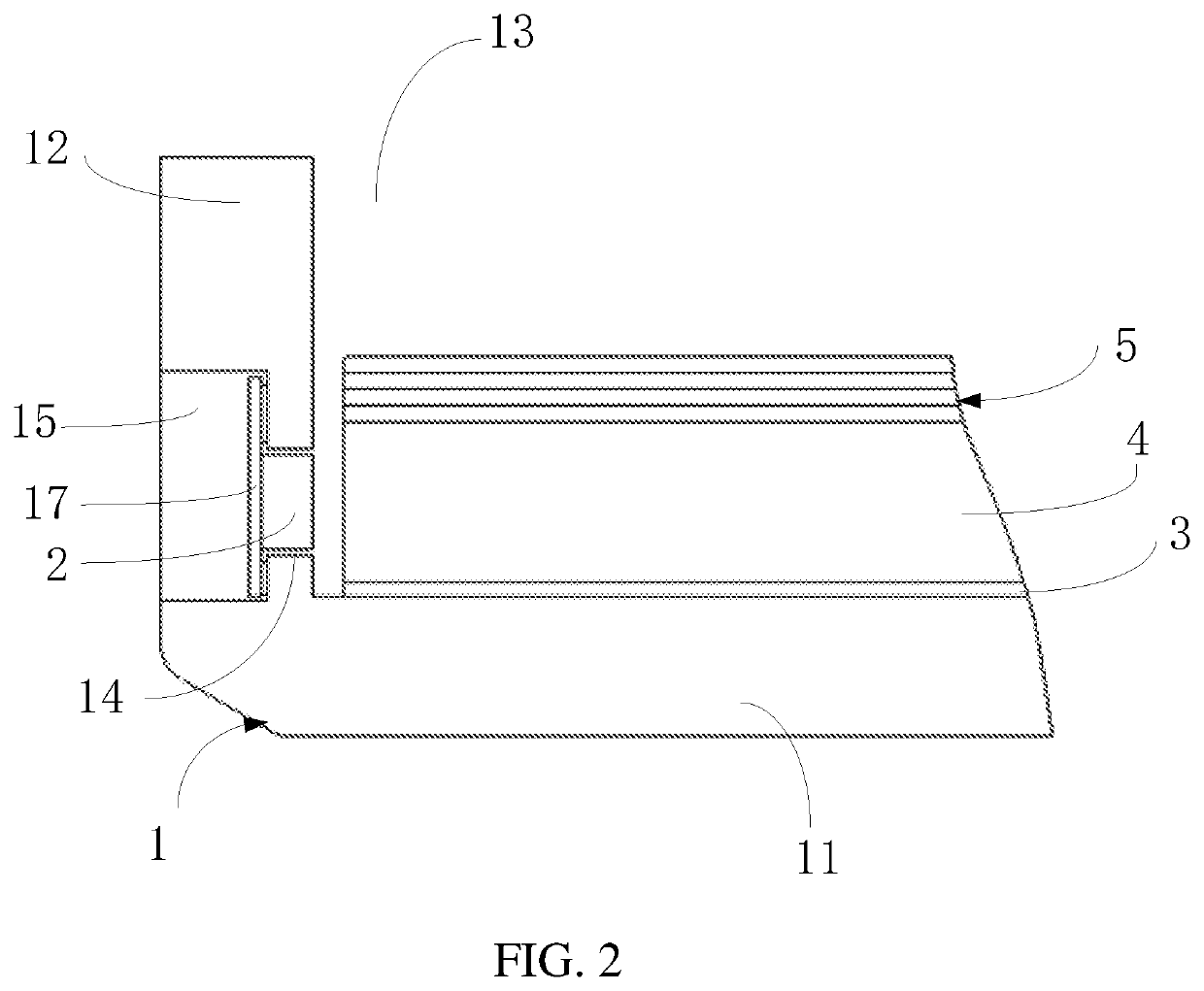
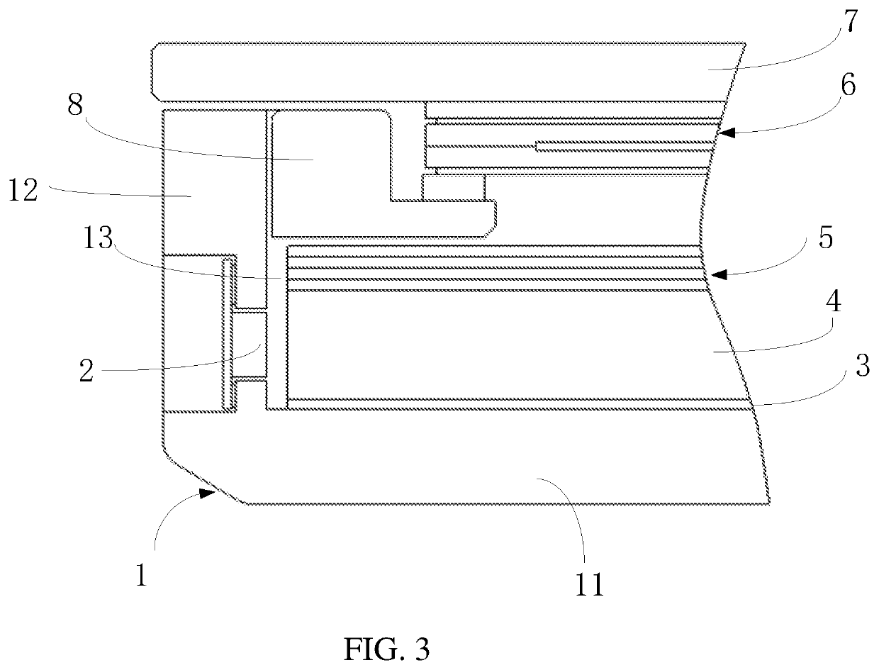
[0027]The preferred embodiments of the present invention are described below with reference to the accompanying drawings, which are used to exemplify the embodiments of the present invention, which can fully describe the technical contents of the present invention to make the technical content of the present invention clearer and easy to understand. However, the invention may be embodied in various forms of embodiments, and the scope of the invention is not limited to the embodiments set forth herein.

[0028]The terms used in the description of the present invention are intended to describe an embodiment, and are not intended to illustrate the concept of the invention. Expressions used in the singular form cover plural forms of expression unless the context clearly dictates otherwise. In the description of the present invention, it is to be understood that the terms such as “include”, “have”, and “include” are intended to describe the possibility of one or more other features, numbers...


PUM

PropertyMeasurementUnit
areaaaaaaaaaaa
widthaaaaaaaaaa
adhesiveaaaaaaaaaa

Abstract

A backlight module and a display device are disclosed. The backlight module includes a light guide plate, a light source, and a bracket. The bracket includes a backplate and a bending portion disposed along a peripheral side of the backplate. An accommodation groove is formed in a space between the backplate and the bending portion and is configured to place the light guide plate. A first groove is disposed on an inner side of the bending portion facing and exposed to the light guide plate, and the light source is disposed in the first groove.

Description

BACKGROUND OF INVENTION1. Field of Invention[0001]The present invention relates to a technical field of display panels, and particularly to, a backlight module and a display device.2. Related Art[0002]With development of display panel technology and automotive technology, automotive low temperature poly-silicon (LTPS) display panels are increasingly used in an automotive field due to their narrow bezel characteristics. Therefore, standards for on-board LTPS display devices are also raised.[0003]In current technology, light sources of display devices are fixed on inner sides of brackets near light guiding plates, so that a sufficient space is reserved between the brackets and the light guiding plates to place the light sources, resulting in a large distance between the brackets and the light guiding plates, thereby causing an increase in width of frames of the display devices adjacent to the light sources.SUMMARY OF INVENTION[0004]The present application provides a backlight module a...

Claims


Application Information

Patent Timeline
Patent Type & Authority Applications(United States)
IPC IPC(8): F21V8/00
CPCG02B6/0066G02B6/0055G02B6/0088G02B6/0086G02F1/133615G02F1/133314G02F1/133308G06F1/1626G06F1/1656B60K35/00B60K2370/1438B60K2370/343B60K2370/336G02B6/0091G02B6/0073
Inventor XIAO, SHIYUAN
Owner WUHAN CHINA STAR OPTOELECTRONICS TECH CO LTD
Why Eureka
Try Eureka