Photoelectric encoder

a technology of photoelectric encoder and encoder, which is applied in the field of photoelectric encoder, can solve the problems of difficult assembly of photoelectric encoder, limited interface size reduction, and difficulty in manufacturing long bundle fibers, and achieves the effect of reducing or eliminating, facilitating the configuration of a long distance optical transmission system, and assembling the photoelectric encoder easily

Active Publication Date: 2011-02-10
MITUTOYO CORP
View PDF9 Cites 1 Cited by
  • Summary
  • Abstract
  • Description
  • Claims
  • Application Information

AI Technical Summary

Benefits of technology

[0007]In a photoelectric encoder according to the above aspect of the invention, the plurality of fibers is partially disposed in the inner space of the first cable in such a manner that the positions of the fibers are fixed relative to one another in a section taken along a plane orthogonal to the direction of the length of the fibers. In addition, the plurality of fibers is partially disposed in the inner space of the second cable in such a manner that the positions of the fibers are variable relative to one another in the section taken along the plane orthogonal to the direction of the length of the fibers. Since such a structure reduces or eliminates need for fixing the fibers for a long distance, which is cumbersome, it is possible to assemble the photoelectric encoder easily. In addition, with such a structure, it is easier to configure a system for long distance optical transmission through the fibers. Moreover, since the plurality of fibers is partially disposed in the inner space of the second cable, which is relatively near the frame unit, in such a manner that the positions of the fibers are variable relative to one another in the section taken along the orthogonal plane, it is easier to optically connect the fibers to the light source and the light-sensitive element, which are provided inside the frame unit. Furthermore, since the plurality of fibers is partially disposed in the inner space of the second cable, which is provided outside the frame unit, in such a manner that the positions of the fibers are variable relative to one another in the section taken along the orthogonal plane, it is not necessary to provide components that are used for unbundling a bundle fiber inside the frame unit. Thus, the size of the frame unit can be reduced. Thus, it is possible to provide a photoelectric encoder that can improve easiness in handling, usability, and work efficiency.

Problems solved by technology

Therefore, it is necessary to manufacture a long bundle fiber, which is not easy.
Thus, the reduction in the size of the interface is limited.

Method used


Image

  • Photoelectric encoder
  • Photoelectric encoder
  • Photoelectric encoder

Examples


Embodiment Construction

[0029]With reference to the accompanying drawings, an exemplary embodiment of the present invention will now be explained in detail. The specific embodiment described below is not intended to limit the scope of the invention recited in the appended claims. Nor is it always necessary to combine all of features described below to provide a means for solving problems including the problems explicitly shown herein.

[0030]A photoelectric encoder according to an exemplary embodiment of the invention is explained below while referring to FIGS. 1 to 5.

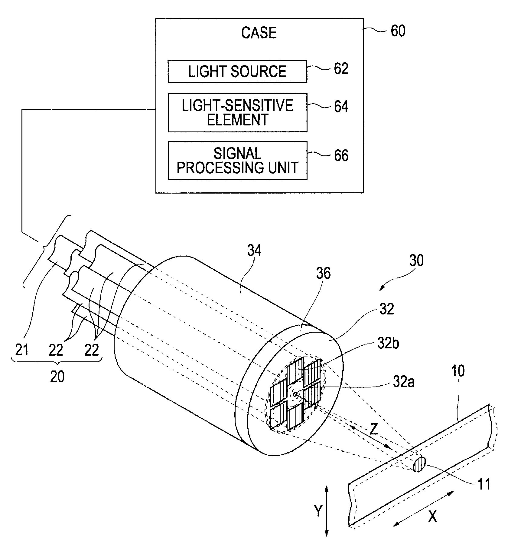
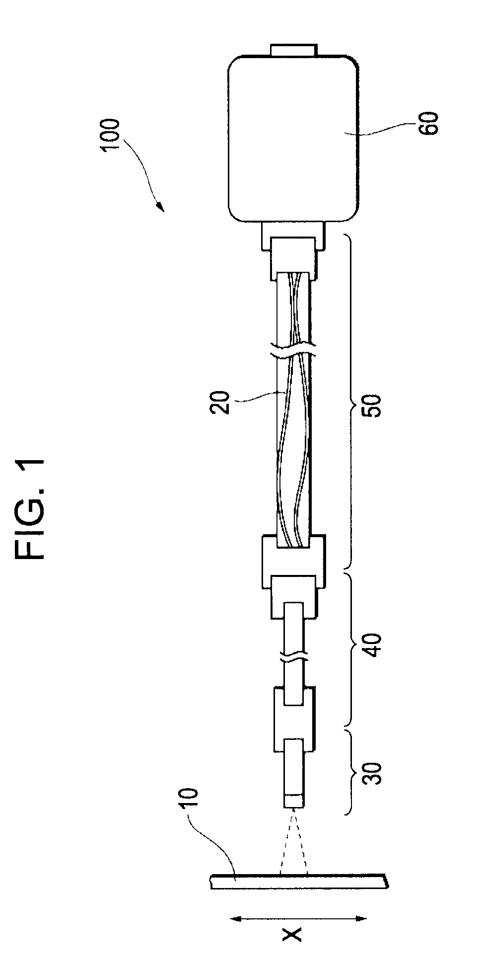
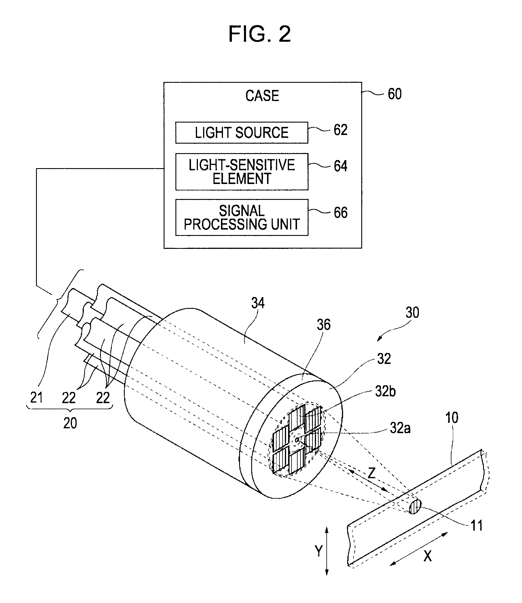
[0031]FIG. 1 is a diagram that schematically illustrates an example of the configuration of a photoelectric encoder according to an exemplary embodiment of the invention. Each of FIGS. 2 to 5 is a detailed view of the photoelectric encoder illustrated in FIG. 1. A photoelectric encoder 100 includes a scale 10, a plurality of fibers 20, a detection head 30, a first cable 40, a second cable 50, and a case 60. A diffraction grating is formed on th...


PUM


Abstract

A photoelectric encoder includes: a scale; a detection head; fibers through which light that is to be irradiated on the scale and light reflected by the scale propagates; first and second cables each having a space in which the fibers are partially disposed; and a case that encloses a light source that supplies light to one of the fibers and a light-sensitive element that receives the reflected light propagating through the others of the fibers and converts the received light into an electric signal. The first cable, the second cable, and the case are disposed in this order in the direction of propagation of the reflected light. The positions of the fibers are fixed relative to one another inside the first cable in the direction orthogonal to the direction of length of the fibers and variable relative to one another inside the second cable in the orthogonal direction.

Description

TECHNICAL FIELD[0001]The present invention relates to a photoelectric encoder.BACKGROUND[0002]A photoelectric encoder generally uses a bundle fiber, which is a bundle of fibers fixed to one another. A photoelectric encoder of related art includes a scale, a light emission fiber, a plurality of light reception fibers, and a detection head. The scale has a diffraction grating formed at a predetermined pitch in the direction of the measurement axis. The detection head, which can change its relative position with respect to the scale, irradiates the scale with coherent light. Light reflected by the scale enters the detection head. The outgoing coherent light propagates through the light emission fiber. The incoming reflected light propagates through the light reception fibers. The light emission fiber is disposed at the center on a detection plane of the detection head. The light reception fibers are disposed around the light emission fiber on the detection plane. The system of related ...

Claims


Application Information

Patent Timeline
Patent Type & Authority Applications(United States)
IPC IPC(8): G01D5/347G01D5/38
CPCG01D5/34723G02B6/3624G02B6/04
Inventor MORI, HIROATSUKAWADA, HIROAKI
Owner MITUTOYO CORP
Why Eureka
Try Eureka